


Page 19 of 38
4 Installation
4-1 Installing the SCC1-5Q Control Panel
Note: Before you mount the panel, consider how you run wiring to
the vacuum receivers, the filter chamber atmospheric valve
(if so equipped) and the pump motor starter(s), vacuum
switch(es), and vent valve(s).
Mount the panel on a flat, vertical area. It should be a visible
area that gives your operator access to the control. The
panel requires a low voltage power drop as listed on the
serial tag.
4-2 Making Electrical Connections
Refer to local electrical codes, the schematic and connection
diagrams supplied with this unit and the serial tag for wiring
considerations. Run all wiring in conduit if codes require it.
4-3 Making SSC1-5Q Control Panel Power Drop Wiring
Connections
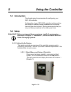
Hardwire the input power at 110/1/50-60 VAC or 230V/1/50-
60 VAC, depending on the specifications, which are located
on the SSC1-5Q Control Panel Serial Tag. The main power
switch is located on the right side of the enclosure.
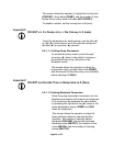
Important! Sterling recommends that you protect PLC memory by providing
the control panel with a dedicated circuit, a true earth ground, and
a spike/surge protector.
4-4 Connecting the Control Panel to Vacuum Receivers
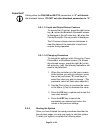
1. On 24 VDC control voltage systems, run a common +24
VDC wire and a common 0 (zero) VDC wire from the
controller to each vacuum receiver in the SSC system.
2. On all systems, run two wires to each vacuum receiver:
one each from the controller to the Bin-Full switch (LS)
and to the Atmospheric/Sequence-T solenoid (SOL)
valve.
3. Make sure that the solenoid and the proximity switch (if
supplied) on vacuum receivers are the same voltage (24