


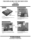
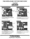
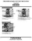
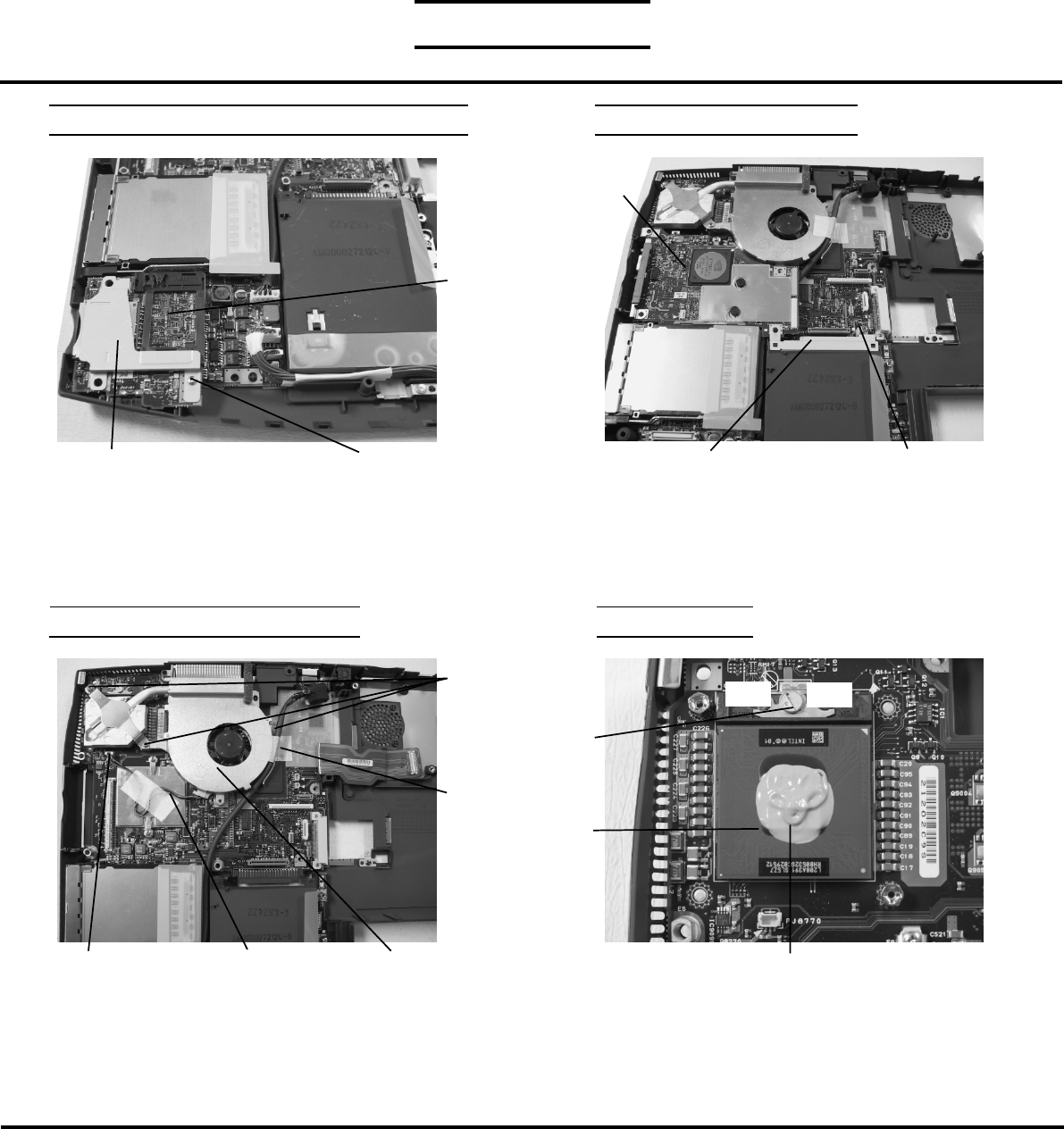
CPU REMOVAL
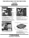
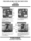
COOLING MODULE REMOVAL
1. Disconnect the fan harness from PJ8770 on the
system board.
2. Remove three M2x8 brass screws and securing the
cooling module to the system board.
3. Peel off the glass tape securing the DC harness and
lift out the cooling module.
FIELD REPLACEABLE UNIT DOCUMENTATION
5100 Series
TOSHIBA
Tough Enough for Today’s World
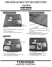
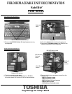
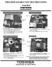
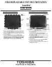
VIDEO BOARD REMOVAL
1. Remove one hex screw securing the HDD con plate
and lift out the plate.
2. Disconnect the video board from system board.
Satellite
TM
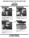
SECURE DIGITAL(SD) BOARD REMOVAL
1. Remove one M2x4 brass screw securing the
SD support plate and the sound FIR board.
2. Remove the SD support plate and lift up the back
side of the sound/FIR board to disconnect it from
PJ601 on the system board.
M2x4 brass screw
SD support plate
Sound/FIR
board
HDD con plate
Hex screw
Video board
Fan harness
Cooling module
M2x8
brass
screws
PJ8770
Glass tape
CPU
1. Insert a flat head screwdriver in the CPU lock and
rotate it counter-clockwise to unlock the CPU.
2. Lift out the CPU.
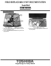
NOTE: When installing the CPU, make sure that a silicone
grease is applied before attaching the heat sink.
Please refer to FSB-200112 for the complete
procedures on how to apply the silicone grease.
CPU
lock
Silicone grease
Open
Close