


6 Freedom SW 2000 Installation Guide
Planning the Installation
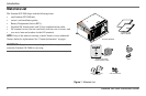
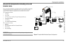
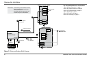
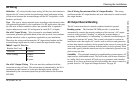
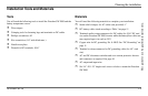
Figure 3
Wiring and Breakers Block Diagram
IMPORTANT: ReadOwner’sandInstallationGuides
prior toinstallation.
Alwaysrefer tolocalandnational
electricalcodes forproperwireand
breakersizesprior toinstallation.
FSW2000
Inverter/Charger
120 VACOUT
120 V AC IN
12volt
Battery(Bank)
4/0 AWG
250 A fuse**
8 AWG Chassis GND
10 AWG
10AWG*
HOT = BLACK
NEUTRAL= WHITE
GND=GREEN/Bare
HOT BUS
HOT BUS
TOACAPPLIANCE
LOADS
INVERTERACSUBPANEL(TYPICAL)
MAINELECTRICALPANEL
FROM SHORE OR
GENERATOR POWE
R
OPTIONAL
GFCIduplex receptacle
15 Aoutput limit
HARDWIRE CONNECTIONS
20 A MAX in inverter
30 A MAX In pass-through
** Class Torequivalent
Neutral
GND
15A
20 A
Neutral
GND
30A
MAIN
For wire and breaker size information:
1.See “AC Input Protection” on page 7.
2.See “AC Output Protection” on page 8.
3.See “GFCI Requirements” on page 8.
4.See “AC Wiring” on page 9.
5.See “DC Cabling” on page 11.
6.See “DC Grounding” on page 11.
1
2
3
4
4
5
6