


975-0171-01-01 xi
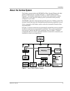
Figure 1 Typical Xanbus System Diagram- - - - - - - - - - - - - - - - - - - - - - - - - - - - - - - 3
Figure 2 Typical Recreational Vehicle Electrical System - - - - - - - - - - - - - - - - - - - - - 7
Figure 3 RS3000 Hardware Materials as Shipped - - - - - - - - - - - - - - - - - - - - - - - - - 15
Figure 4 Mounting Orientations- - - - - - - - - - - - - - - - - - - - - - - - - - - - - - - - - - - - - 20
Figure 5 AC Wiring Compartment - - - - - - - - - - - - - - - - - - - - - - - - - - - - - - - - - - - 22
Figure 6 DC Cable Connections- - - - - - - - - - - - - - - - - - - - - - - - - - - - - - - - - - - - - 28
Figure 7 DC Terminal Covers - - - - - - - - - - - - - - - - - - - - - - - - - - - - - - - - - - - - - - 28
Figure 8 Completed DC Wiring and DC Grounding - - - - - - - - - - - - - - - - - - - - - - - 29
Figure 9 BTS with Cable - - - - - - - - - - - - - - - - - - - - - - - - - - - - - - - - - - - - - - - - - 30
Figure 10 BTS Mounted on the Negative Battery Terminal - - - - - - - - - - - - - - - - - - - 31
Figure 11 Connecting the BTS Cable to Battery Temp. jack- - - - - - - - - - - - - - - - - - - 32
Figure 12 BTS Mounted on the Battery Case- - - - - - - - - - - - - - - - - - - - - - - - - - - - - 33
Figure 13 Connecting to a Network Jack- - - - - - - - - - - - - - - - - - - - - - - - - - - - - - - - 34
Figure 14 RS3000 Front Panel - - - - - - - - - - - - - - - - - - - - - - - - - - - - - - - - - - - - - - 36
Figure 15 Inverter/Charger Dimensions - - - - - - - - - - - - - - - - - - - - - - - - - - - - - - - - 39
Figure 16 Batteries Connected in Parallel - - - - - - - - - - - - - - - - - - - - - - - - - - - - - - - 44
Figure 17 Batteries Connected in Series - - - - - - - - - - - - - - - - - - - - - - - - - - - - - - - - 45
Figure 18 Batteries in Series-Parallel Connections - - - - - - - - - - - - - - - - - - - - - - - - - 46
Figures