


Installation
975-0171-01-01 17
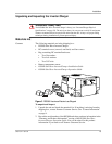
Installing the Inverter/Charger
Overview
This section provides detailed information on installing the RS3000. The overall
procedure is divided into eight steps:
Step 1: Choosing a Location for the Inverter/Charger
Step 2: Mounting the Inverter/Charger
Step 3: Connecting the AC Input and AC Output Wires
Step 4: Connecting the DC Cables
Step 5: Connecting the Battery Temperature Sensor (BTS)
Step 6: Connecting to the Network
Step 7: Performing Checks Prior to Initial Start-Up
Step 8: Testing Your Installation
Step 1: Choosing a Location for the Inverter/Charger
The location of the inverter/charger is a key factor in system performance.
Allow sufficient clearance around the unit (recommended minimum 3 inches
(76 mm)) and install in a well-ventilated compartment to prevent overheating and
premature shutdown of the inverter/charger.
The inverter should only be installed in a location that meets the following
requirements:
WARNING: Risk of fire or explosion
This equipment contains components that could produce arcs or sparks. To reduce the risk
of fire or explosion, do not install this equipment in compartments containing batteries or
flammable materials, or in locations that require ignition-protected equipment. This
includes any space containing gasoline-powered machinery, fuel tanks, or joints, fittings,
or other connections between components of the fuel system.
WARNING: Fire hazard
Do not cover or obstruct the ventilation openings. Do not install this equipment in a
compartment with limited airflow. Overheating may result.
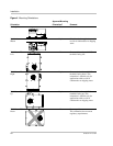
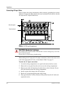
Ventilated Do not operate the inverter/charger in a closed-in area or restrict
ventilation in any way. The inverter/charger requires air circulation
to maintain optimum operating temperature and provide best
performance. If the unit has inadequate ventilation, it may shut down
due to overheating.
The air vented through the openings should also have a path to
circulate away from the inverter/charger.