


A
AC and DC wiring separation 21
AC input wiring connections 22
AC input, defined 8
AC knockout dimensions 21
AC output neutral bonding 12
AC output wiring connections 24
AC wiring
defined
10
size 11
type 10
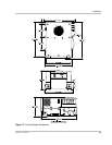
AC wiring compartment, illustrated 21
AC wiring considerations 21
AC wiring terminal, illustrated 21
B
batteries 13
battery temperature sensor
cable length
30
function of 30
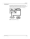
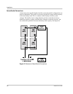
mounted on negative battery terminal 31
mounted to battery case 33
two mounting options 30
BTS. See battery temperature sensor 30
C
clearance around unit, recommended vi, 17, 18
connecting to the network, precaution 34
Customer Service
email
iii
fax number iii
phone number iii
D
DC cable, required size and length 14
DC cabling, required 14
DC disconnect device 13
DC fuse size, required 14
DC grounding 14
DC over-current device 13
F
FCC, regulations viii
G
gases, hydrogen 18
GFCI 9
GFCI models, tested 10
ground fault circuit interrupter. See GFCI. 9
I
installation
approved mounting orientations
19
approved mounting orientations, illustrated 20
choosing a location for inverter/charger 17
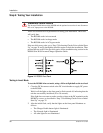
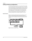
connecting AC input wires 21
connecting AC output wires 21
connecting BTS cable to BTS jack 33
connecting cables to inverter/charger 27
connecting DC cables 25
connecting the battery temperature sensor (BTS) 30
DC grounding 29
mounting the inverter/charger 19
performing checks prior to initial start-up 35
routing DC cables 26
testing in charge mode 37
testing in invert mode 36
tests 36
installation codes
Canadian Electrical Code (CEC)
2
Canadian Standards Association (CSA) 2
RV Industry Association (RVIA) 2
U.S. National Electrical Code (NEC) 2
inverter/charger, heavy load precaution 19
M
materials list 15
materials, installation 16
R
related product literature iii
S
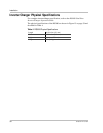
specifications
inverter
38
physical 38
strain relief, size of 21
Index