5HIHUHQFH0DQXDO
00809-0100-4811, Rev AA
October 2002
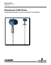
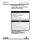
Rosemount 3300 Series
Index-2
3
Power Requirements . . . . . . 3-17
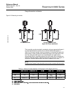
Probe
anchoring
. . . . . . . . . . . 3-14
shortening . . . . . . . . . . 3-12
Probe Angle . . . . . . . . . . . . 4-11
Probe angle . . . . . . . . . . . . . 4-4
Probe Length . . . . . . . . 4-3, 4-9
Probe Type . . . . . . . . . 4-3, 4-10
Process connection . . . . . . . . 3-6
Product Dielectric . . . . . . . . . 4-10
5
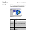
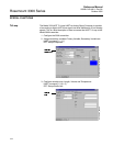
Radar Configuration Tool . . . 4-14
RCT . . . . . . . . . . . . . . . . . . 4-14
COM Port . . . . . . . . . . . 4-14
installing . . . . . . . . . . . . 4-14
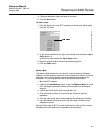
Logging . . . . . . . . . . . . 6-15
Logging the plot . . . . . . . 6-4
Saving the configuration . 6-16
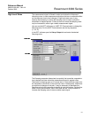
Setup . . . . . . . . . . . . . . 4-17
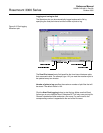
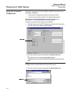
Waveform Plot . . . . . . . . 6-3
Wizard . . . . . . . . . . . . . 4-16
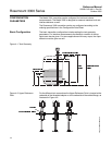
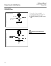
Recommended mounting position .
3-10
Reference Gauge Height 4-3, 4-9
6
Setup
Basic
. . . . . . . . . . . . . . 4-18
LCD . . . . . . . . . . . . . . . 4-23
Output . . . . . . . . . . . . . 4-19
Save configuration . . . . . 6-16
Tank Config . . . . . . . . . 4-20
Volume . . . . . . . . . . . . 4-22
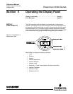
Shift Keys . . . . . . . . . . . . . . .C-7
Standard Tank Shapes . . . . . . 4-6
Strapping Table . . . . . . . . . . 4-13
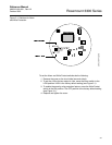
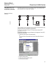
System Architecture . . . . . . . . 2-5
7
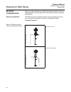
Tank connection
flange
. . . . . . . . . . . . . . 3-11
threaded . . . . . . . . . . . . 3-11
Tank Dimensions . . . . . . . . . 4-13
Tank geometry . . . . . . . . . . . 4-2
Tank Type . . . . . . . . . . . . . . 4-13
Time Domain Reflectometry . . 2-1
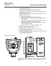
Transmitter Head
removing
. . . . . . . . . . . 6-18
Transmitter housing . . . . . . . . 2-4
Transmitter Reference Point . . 6-2
Transmitter Switch Settings . . 3-4
Transmitter Units . . . . . . . . . . 4-9
Transmitter Variables . . 4-9, 4-13
Tri-Loop . . . . . . . . . . . . . . . 4-24
Troubleshooting . . . . . . . . . 6-19
8
Upper Dead Zone . . . . . . . . . 2-7
Upper Null Zone . . . . . .4-3, 6-12
Upper Reference Point . .4-2, 6-2
9
Vapor . . . . . . . . . . . . . . . . . . 2-8
Vapor Dielectric . . . . . . . . . 4-10
Vessel characteristics . . . . . 2-10
Volume Configuration . . . . . 4-13
Volume Units . . . . . . . . . . . 4-13
:
Waveform plot . . . . . . . . . . . 6-3
Write Protect switch . . . . . . . . 3-5
Write Protection . . . . . . . . . . 5-2