5HIHUHQFH0DQXDO
00809-0100-4811, Rev AA
October 2002
4-19
Rosemount 3300 Series
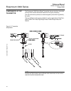
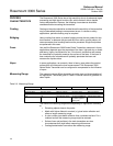
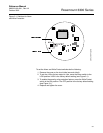
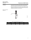
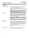
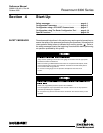
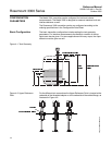
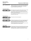
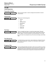
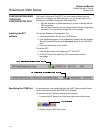
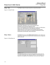
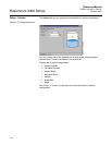
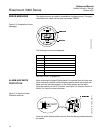
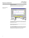
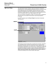
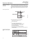
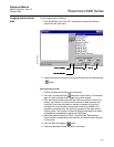
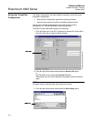
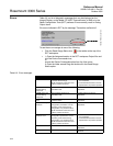
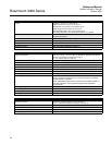
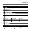
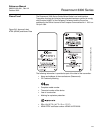
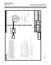
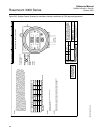
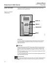
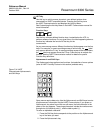
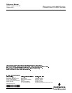
6HWXS2XWSXW The 2XWSXW tab lets you assign up to four transmitter variables
Figure 4-15. Setup output tab
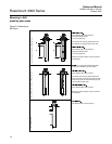
Typically, the 3ULPDU\9DULDEOH (PV) is configured to be Product Level,
Interface Level or Volume.
Other variables like Product Distance, Interface Distance, Upper Product
Thickness, etc. are available as well.
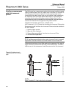
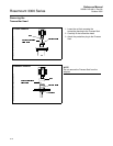
For model 3301 the primary variable is typically set to be Level. If the
transmitter is in the Immersed Probe mode (see section
“Measurement Mode” ) the PV is normally set to Interface Level.
For the model 3302 the PV is typically set to Interface Level, but Level and
other options may also be used.
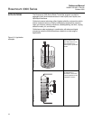
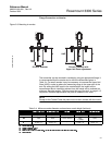
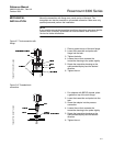
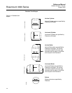
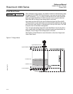
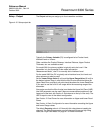
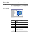
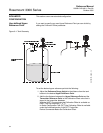
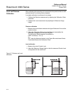
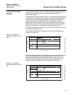
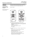
Set the /RZHU5DQJH9DOXH (4 mA) and the 8SSHU5DQJH9DOXH (20 mA) to
the desired values. Keep in mind that the 20 mA value should be below the
Upper Dead Zone, and the 4 mA point should be above the Lower Dead Zone
if you want to use the full 4-20 mA range within the measuring range of the
transmitter.
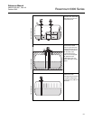
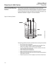
Also make sure that the 20 mA value is set below the Upper Null Zone (UNZ).
(the UNZ parameter may be used if there are measurement problems in the
upper part of the tank, see 6HFWLRQ'LVWXUEDQFHVDWWKHWRSRIWKHWDQN). The
UNZ is equal to zero in the default configuration.
See 6HFWLRQ'HDG=RQHV for more information on Upper and Lower Dead
Zones.
See 6HFWLRQ%DVLF&RQILJXUDWLRQ for more information on setting the Upper
and Lower Range values.
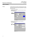
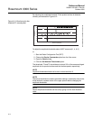
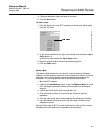
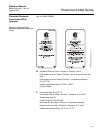
The default 'DPSLQJ value is 10. Normally this value does not need to be
changed. The Damping parameter may be changed if there are high filling
rates, see “High Level Rates” on page 6-7 for more information.
RCT-SETUP_OUTPUT