5HIHUHQFH0DQXDO
00809-0100-4811, Rev AA
October 2002
4-25
Rosemount 3300 Series
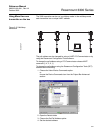
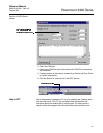
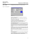
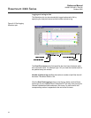
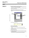
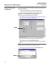
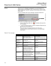
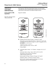
4. Put the 3300 in Burst mode.
HART command [1, 4, 5, 2, 3].
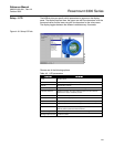
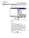
RCT: Device Commands>Details>Set Burst Mode option.
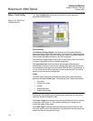
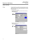
5. Select Burst option 3=Process variables and current (Process vars/crnt).
HART command [1,4,5,2,4].
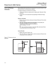
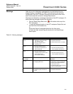
6. Install the Tri-Loop. Connect channel 1 wires, and optionally wires for
Channel 2 and Channel 3.
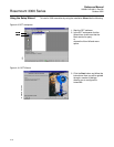
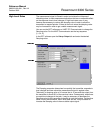
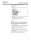
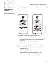
7. Configure Tri-Loop Channel 1:
a. Assign variable: Tri-Loop HART command [1,2,2,1,1].
Make sure that the SV, TV, and QV match the configuration of the
3300 transmitter.
b. Assign units: Tri-Loop HART command [1,2,2,1,2]. Make sure that
the same units are used as for the 3300 transmitter.
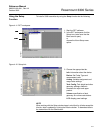
c. Set the Upper Range Value and the Lower Range Value: Tri-Loop
HART command [1,2,2,1,3-4].
d. Enable the channel. Tri-Loop HART command [1,2,2,1,5].
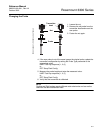
8. (Optional) Repeat steps a-d for Channels 2 and 3.
9. Connect wires to Tri-Loop Burst Input.
10. Enter the desired tag, descriptor and message information:
Tri-Loop HART command [1,2,3].
11. (Optional) If necessary, perform an analog output trim for Channel 1 (and
Channel 2 and 3 if they are used).
Tri-Loop HART command [1,1,4].
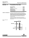
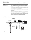
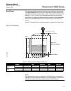
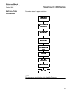
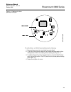
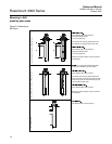
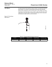
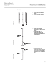
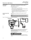
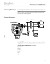
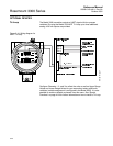
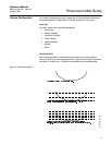
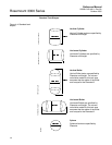
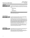
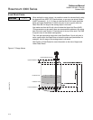
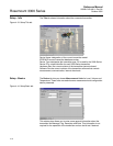
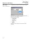
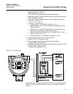
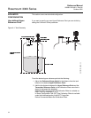
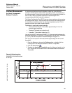
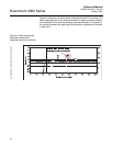
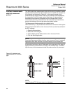
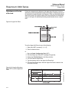
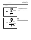
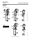
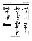
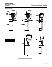
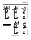
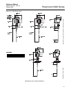
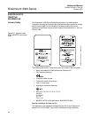
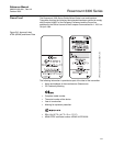
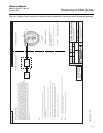
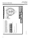
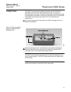
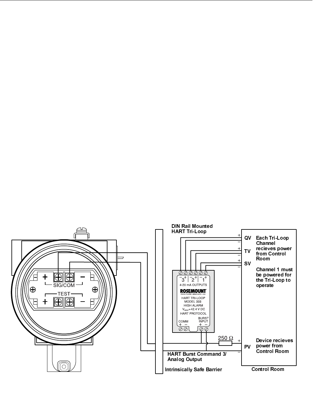
Figure 4-19. Tri-Loop wiring.
See the reference manual for the 0RGHO+$577UL/RRS+$57WR$QDORJ
6LJQDO&RQYHUWHU for further information on how to install and configure the
Tri-Loop.
WIRING TRILOOP333