


2-28
Chapter 2: Hardware information
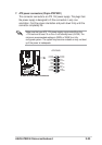
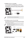
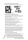
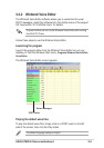
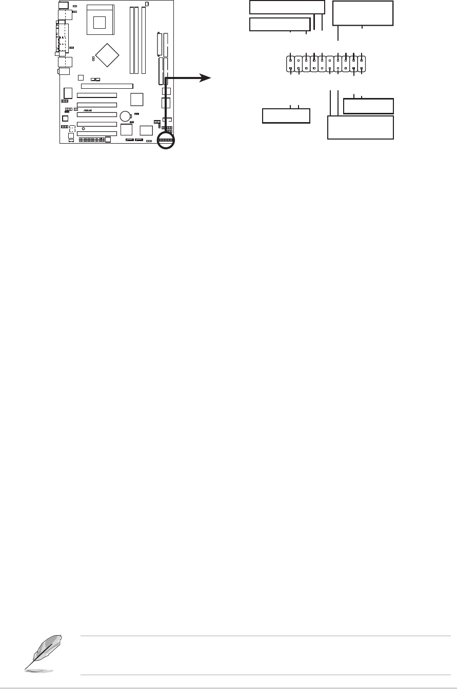
15. System panel connector (20-pin CTRL_PANEL1)
This connector accommodates several system front panel functions.
• System Power LED Lead (Green 3-1 pin PLED)
This 3-1 pin connector connects to the system power LED. The LED
lights up when you turn on the system power, and blinks when the
system is in sleep mode.
• Keyboard Lock Lead (Brown 2-pin KEYLOCK)
This 2-pin connector connects to a chassis-mounted switch to allow
the use of the keyboard lock feature.
• System Warning Speaker Lead (Orange 4-pin SPKR)
This 4-pin connector connects to the case-mounted speaker and
allows you to hear system beeps and warnings.
• Reset Switch Lead (Blue 2-pin RESET)
This 2-pin connector connects to the case-mounted reset switch for
rebooting the system without turning off the system power.
•ATX Power Switch / Soft-Off Switch Lead (Yellow 2-pin PWRBTN)
This connector connects a switch that controls the system power.
Pressing the power switch turns the system between ON and SLEEP,
or ON and SOFT OFF, depending on the BIOS or OS settings.
Pressing the power switch while in the ON mode for more than 4
seconds turns the system OFF.
• Hard disk activity LED (Red 2-pin IDE_LED)
This connector supplies power to the hard disk activity LED. Any read
or write activity of an IDE device cause this LED to light up.
The System Panel connector is color-coded for easy and foolproof
connection. Take note of the specific connector colors as described.
A7N8X-E
®
A7N8X-E System Panel Connectors
* Requires an ATX power supply.
PLED-
PWR
PLED+
Keylock
+5V
Speaker
Speaker
Connector
Power LED
Ground
Reset SW
GND
Reset
Ground
Ground
Ground
Keyboard Lock
ATX Power
Switch*
IDE_LED-
IDE_LED+
IDE_LED