


3-10 Receiving & Installation MN1853
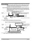
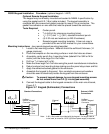
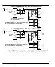
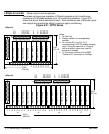
Figure 3-13 RS485 4 Wire Multi-Drop for UL Installations
* Terminating resistor T
R
is 120 W typical value. Only
the PC and last control are terminated.
TX+
TX–
DGND
GND
TX+
TX–
Shields
DGND
GND
*
RX+
RX–
DGND
GND
T
R
*
T
R
TX+
TX-
RX+
RX-
RX+
RX-
Use twisted pair shielded cable
with an overall shield.
P
= Twisted Pair
P
P
Shields
*
T
R
*
T
R
First
Unit
Last
Unit
PC / Host
Device
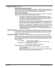
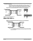
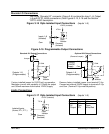
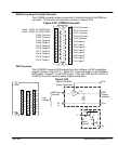
Figure 3-14 RS485 4 Wire Multi-Drop for CE Installations
* Terminating resistor T
R
is 120 W typical value. Only
the PC and last control are terminated.
TX+
TX–
DGND
GND
TX+
TX–
DGND
GND
*
RX+
RX–
DGND
GND
T
R
*
T
R
TX+
TX-
RX+
RX-
RX+
RX-
Use twisted pair shielded cable
with an overall shield.
P
= Twisted Pair
P
P
PE
PE
PE
PE
*
T
R
*
T
R
First
Unit
Last
Unit
PC / Host
Device
Note: For CE installations, connect the overall shield at each end of the cable to PE. The
voltage potential between the PE points at each end of the cable must be Zero Volts.