


Setup 5-11MN1853
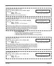
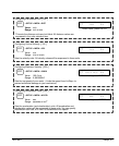
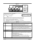
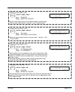
Figure 5-1
4
3
2
1
Data Valid
Unit
Selection
PLC
Program
Selection
LinStep
#1
LinStep
#2
LinStep
#3
LinStep
#4
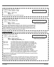
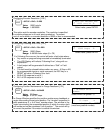
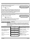
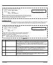
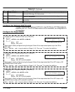
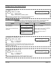
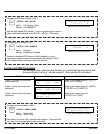
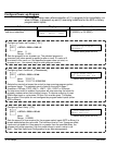
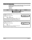
Configuring Output Definition [ ODaaaaaaaa ]
EDIT
> SETUP > I/O > OUTPUTS
Value: PPPPPPPP
Range:
OUT1: PROGRAMMABLE
P
PPPPPPP ←↑↓→
Each input is easily configured using the keypad as described in Table 5-2. The
function of each input channel is indicated by a letter at the bottom of the display.
Note: Use the ← and → keys to select an Input. Then use ↑↓ to select the
definition for each input (described in Table 5-2).
Note: Lower case Input Characters (b, d, h, k and m) appear on the Keypad but
are not used.
Select value, press ENTER
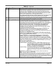
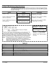
Table 5-2
Char Keypad Display Input Character Description
A AMP FAULT Amplifier Fault – Output goes low on any amplifier fault. An amplifier fault may
be due to temperature, motor short–circuits, excessive following error,
over–voltage and excessive regeneration conditions.
Note: This is not an all–inclusive fault output. Use F–Fault for this.
B BRAKE It is often advisable that applications using a ball screw type actuator with a
vertical load use a brake to prevent the load from falling in the event of a fault.
The Brake output is normally disengaged, which is actually an ON condition.
When a fault occurs, power to the brake is removed and the brake is
engaged. This is a “fail–safe” type of brake, controlled by an OPTO module,
and it requires a customer supplied, 120VAC power supply, or 24 VDC with B
Motors.
C OVER CURRENT Not Used.
D DIRECTION The output remains set until motion is commanded in the reverse direction.
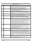
F FAULT The fault output acts as an all–inclusive fail–safe output. Under normal
operation the output is low (ON) and goes high (OFF) when any type of fault
occurs. A fault can occur from any amplifier fault condition (A) as well as for
the following general faults:
S BMA (Board Monitor Alarm) time–out
S Error finding Home – both limits were hit.
The exact cause of the fault can be determined a number of ways:
S Shown on keypad display
S RS–232C using the SS, SD, and SA status commands (see Appendix A)
S Other outputs can be configured to show more specific fault states
H AT HOME The output goes high as long as the axis is at home.