


Section 7
Troubleshooting
Troubleshooting 7-1MN1853
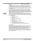
Overview The system troubleshooting procedures involve observing the status of the LED’s.
The tables in this section provide information related to the indications provided by
these devices.
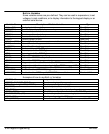
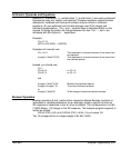
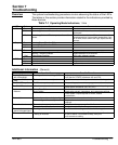
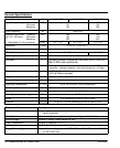
Table 7-1 Operating Mode Indications, 1 Axis
LED Color Status Comments
ON Green Power is applied. Not a failure.
Yellow Power is applied and “Shutdown” was issued. Not a failure if Indexer issued a valid shutdown
command.
Red Power is applied and “Overtemperature” condition
exists.
Allow driver to cool down. Determine reason for
overtemperature, high ambient temperature, lack
of air flow, motor current too high, adjust standby
current.
Step Green Incoming Steps, Direction CW Not a failure.
Yellow Incoming Steps, Direction CCW Not a failure.
Red
Bus Green
Yellow Continuous on=overvoltage condition
Flashing = Regen condition
Verify input voltage is proper. Not a failure.
Regen operation is not a failure.
Red Undervoltage condition Verify input voltage is proper
FLT Green
Yellow Interlock condition. Verify motor connections.
Red Motor short. Replace motor.
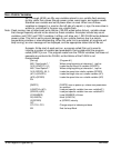
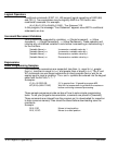
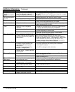
Additional Information (General)
Symptom Possible Cause Possible Remedies
The keypad is blank
with no backlight.
The keypad is not receiving +5VDC. Verify all wiring is correct.
Verify that the +5VDC is between 4.8 and 5.2V.
Display is difficult to
read
Contrast ratio is incorrectly set Adjust the contrast with the pot on the back of the keypad.
The ON LED is yellow. FLASH memory is corrupt. The operating system and user programs must be reloaded.
The ON LED is red. A Fault has occurred. The fault can be determined with the keypad or by using
serial status commands (SS, SA, SD).
Motor moves the wrong Wrong Gear Ratio. Check distance units
distance
Motor stalled. Check motor current, inductance, anti–resonance settings
Check Speed Torque required for move, reduce
acceleration.
Motor stalls Acceleration and/or velocity too high. Reduce acceleration and/or velocity.
Motor configured incorrectly. Check motor current, inductance and anti–resonance
settings.
Motor direction is wrong The motor phases are miswired. Verify connections, or swap A+ with A–.
The system real direction is reversed. Change the control’s direction parameter.
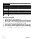
The control does not re-
spond to keypad input.
The keypad is disabled. Check the switch settings on the back of the keypad.
The motor “whines” The inductance or anti–resonance
setting is incorrect.
Verify the Inductance setting. Operation is best with motors
4 mH or above. If this does not help, verify the
anti–resonance setting.