


Section 1
General Information
Receiving & Installation 3-15MN1853
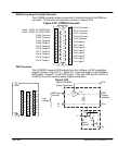
DB25 Pin to Screw Terminal Converter
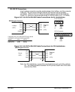
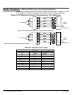
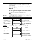
The LXDB25 converter allows connection of individual wires to the DB25 pin
connector. The terminal configuration is shown in Figure 3-22.
Figure 3-22 LXDB25 Converter
Pin1: Input 1
Pin2: Input 2
Pin3: Input 3
Pin4: Input 4
Pin5: Input 5
Pin6: Input 6
Pin7: Input 7
Pin8: Input 8
Pin9: Common
Pin10: Common
Pin11: Common
Pin12: Common
Pin13: Common
Pin14: Output 1
Pin15: Output 2
Pin16: Output 3
Pin20: Output 7
Pin21: Output 8
Pin22: Common
Pin17: Output 4
Pin18: Output 5
Pin19: Output 6
Pin23: Common
Pin24: +5VDC for LXOPTO Box
Pin25: +5VDC for LXOPTO Box
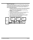
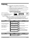
PNP Converter
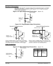
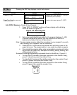
The LXPNPBO converts NPN outputs from the LinStep+ to PNP compatible
outputs, shown in Figure 3-23. Inputs IN1–8 connect directly to the LinStep+
NPN inputs. Outputs 1–8 are PNP outputs. PUp and COM are the 12VDC or
24VDC pull up and common power supply connections.
Figure 3-23
O8
O7
O6
O5
Com
O4
O3
O2
O1
PUp
PUp
Com
Com
Com
Com
Com
PUp
PUp
IN8
IN7
IN6
IN5
Com
IN4
IN3
IN2
IN1
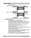
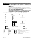
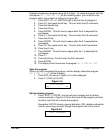
Typical LXPNPBO
Output Connection
PUp
PNP
Output
Terminal
Com
NPN Input
Terminal
Co
m
From
LinStep+
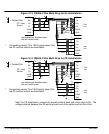
U1
In Out
V
s
In
Out
V
s
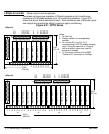
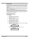
U1
Detail
Typical
10k
7.2k
3k
7.2k