


224
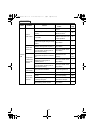
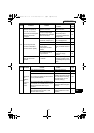
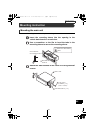
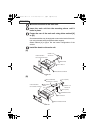
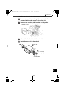
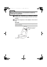
Mounting instruction
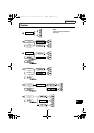
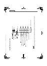
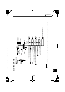
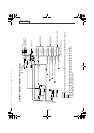
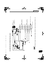
Names of lead wires and destinations
(refer to Page 227)
● Caution ●
Never connect the power supply to the speaker leads, otherwise it
causes damage to the main unit.
● Note ●
To prevent unconnected leads from shorting out, insulate them by
wrapping their tips with electrical tape. Similarly, insulate the ends
of connected leads.
If an external amplifier is to be connected to the receiver, be sure
to ground its outside housing to the vehicle body (a metal part).
No. Name Wire color Destination
1 ACC Red Connect where the power comes
on when the ignition is in the
ACC position.
2 B+ Yellow Connect where the power is
constantly available, regardless
of the ignition switch's position.
3 Ground Black Connect where good body
grounding is available.
4 Antenna power supply Blue Connect to the automatic-
antenna control terminal of the
vehicle.
5 Illumination power
supply
Orange/white Connect to where power comes
on when the headlights are
turned on.
6 Control power supply Blue/white Connect to the control terminal
for the external amplifier, etc.
7 E-LAN terminal Connect to the E-LAN terminal of
the CD changer, etc.
8
9
Line-out terminals (Front/Hi)
Line-out terminals (Rear/Mid)
Connect to the RCA input
connectors of an external
amplifier.
10 Line-out terminals (Nonfader/Low) Connect to the RCA input
connectors of a EQ, or the RCA
input connectors of a woofer
amplifier.
11 Speaker leads Connect them to their respective
leads.
CD8455.book 224 ページ 2004年12月11日 土曜日 午後7時24分