


MLT 2 / BINOS
®
100 F
ATEX Instruction Manual
ETC01035
August 2005
Emerson Process Management Manufacturing GmbH & Co. OHG2 - 16
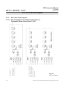
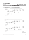
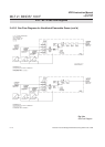
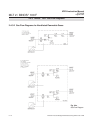
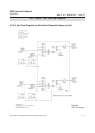
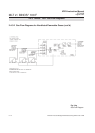
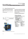
2-7 Electrical Connections
• All connections have to be done accor-
ding to the schematics delivered together
with the equipment.
• A mains switch or ciruit-breaker must be
provided at the building installation.
• The equipment enclosure must be
connected to an earthing or equipotential
bonding conductor.
• All cables introduced into the enclosure
must be kept as short as possible.
• The cable glands are designed to fix
single cables only, with diameters from 7
to 12 mm. Special inserts are available
on request to fix thinner or multiple cables
within one gland.
• Mains power terminals are suitable for
cables up to 2.5 mm
2
cross section.
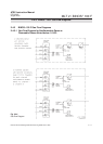
• Use only shielded cables for signal lines!
To ensure proper electromagnetic
compatibility (EMC) it is recommended
to follow the installation steps given in
section 2-7-1!
• Cables carrying intrinsically safe (EEX i)
signals need adequate marking. When
running such cables take into
consideration the requirements given in
the related standards (minimum distance
to non-IS cables etc.). If running in
minimum distance is not possible
clearance may be achieved utilizing so-
lid insulation of suitable thickness.
2-7 Electrical Connections
Installation of and connecting
the power supply lines and
signal lines is permitted to
qualified personnel only!
The standard EN 60079-14
„Electrical Installations in
Hazardous Areas“ and all
related standards have to be
observed.
Failure to follow the proper
instructions may cause any one
of the following situations to
occur: Loss of life; personal
injury; property damage;
damage to this instrument; and
warranty invalidation.