


Maintaining the Test Tool
Calibrating the Voltage Probes
8
79
Repeat steps 2 and 3 and proceed as follows:
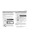
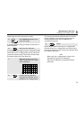
5 Select Probe Cal with the arrow
keys, then accept.
A message appears asking you whether to start the 10:1
probe calibration.
6 Start the probe calibration.
A message appears telling you how to connect the probe.
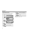
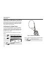
Connect the red 10:1 voltage probe from the red input A
jack to the red banana jack. Connect the reference lead
to the black banana jack. (See Figure 50.)
7 Adjust the trimmer screw in the
probe housing until a pure square
wave is displayed.
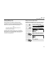
8 Continue with DC calibration.
Automatic DC calibration is only
possible for 10:1 voltage probes.
The test tool automatically calibrates itself to the probe.
During calibration you should not touch the probe. A
message indicates when the DC calibration has
completed successfully.
9 Return.
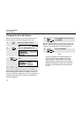
Repeat the procedure for the gray 10:1 voltage probe.
Connect the grey 10:1 voltage probe from the grey input
B jack to the red banana jack. Connect the reference lead
to the black banana jack.
Note
When using 100:1 voltage probes, choose 100:1
attenuation to perform a HF adjustment.
Automatic dc calibration is not possible with this
probe type.