3-2
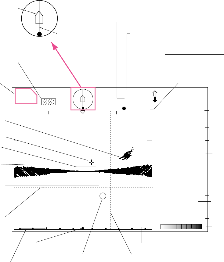
3.2 Typical Vertical Fan Mode Display
+→6
↓ 145
R → 60 m
↓ 100 m
340˚
Cursor position
data
Horizontal range
Vertical range
Event marker
Interference
rejector ON
Heading*
60
60
Horizontal range scale
Bearing indicator
(Shows training direction.)
STARBOARD
PORT
FORE
AFT
Own
ship
Training indicator
FORE AFT
Sector center
indicator
Fish echo
Bottom
echo
Cursor
100
Depth
Vertical range scale
56
Horizontal
marker
Horizontal range marker
CSE 357˚
SPD 9.9 kt
DEP
35 m
TMP
12.3˚C
CUR 11.0˚
2.0 kt
GAIN 5.3
34° 12. 343' N
134° 34. 213' W
TVG LEVEL 4.0
DISTANCE 200 m
COLOR
Position in latitude*,
longitude*
Course*, speed*
Depth
Tide direction*,
tide speed*
Gain setting
TVG level,
distance settings
Color bar
Water temperature*
* Requires appropriate
sensor.
20
Horizontal
range
Transducer status indicator
Filled arrow: Respective action completed
Blinking arrow: Action in progress
Sweep indicator
(Shows tilt angle
in vertical fan mode.)
Figure 3-2 Typical vertical fan mode display


