


6
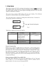
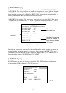
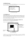
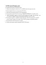
7) ALARM display
This menu sets the ALARM port signal. When ALARM MODE is set to “STOP,” the
alarm signal is not sent out after acknowledgement. When selected “Continue,” the system
continues to output the alarm signal.
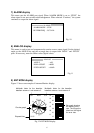
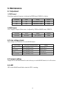
8) ANALOG display
This menu is used to test and compensate the motion sensor output signal. Set the desired
angle on the ANGLE line and the set angle data is output from “ROLL” and “PITCH”
ports. If necessary, enter the Offset value (digital value).
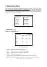
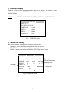
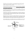
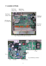
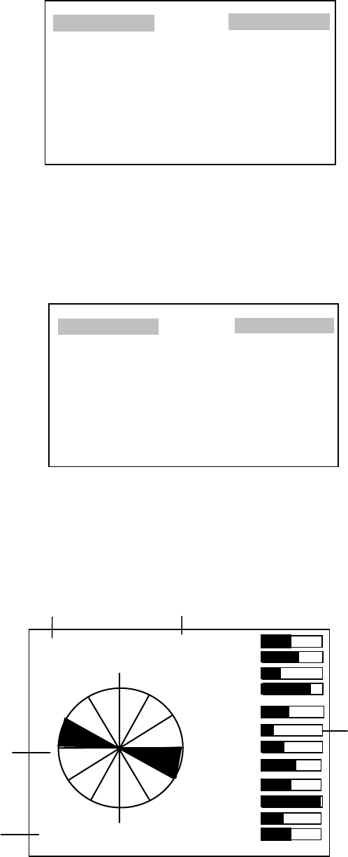
9) ANT MONI display
Figure 12 shows an example of Antenna Monitor display.
1.01 BOW 0.91 01
02
03
04
05
06
07
08
09
10
11
12
11
1
2
3
4
5
67
8
9
10
11
12
95:55
Multipath Index for the baseline
between antenna 1 and antenna 2
Multipath Index for the baseline
between antenna 1 and antenna 3
Elapsed time
Circular graph
Bar graph showing
the tracking error
rate. The longer the
black bar, the higher
the error rate.
Fig.12 ANT MONI display
ALARMS
ALARM MODE : STOP
BUZZER FREQ : 2.075 kHz
Fig. 10
ANALOG
ANGLE : +00º
ROLL OFFSET : +000D
PITCH OFFSET : +000D
Fig. 11