


15
J2 to J7
Appendix 1 Protection of ICs in Data Output Circuit
Appendix 1 describes how to prevent ICs in the data output circuit temporarily.
Refer to Appendix 2 for permanent remedy.
Symptom
U1, U2, and U3 in the heading output circuit are damaged.
Cause
Ground potential difference - The cable shield, or a signal return path between
the circuit grounds of the equipment is not connected securely. The shield is
connected to the unit through the cable clamp on SC-50/110, while the
connector pin is used on SC-60/120.
Remedy
At installation: Carry out 1) to 4).
When the symptom occurs: Carry out 1) to 5).
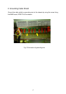
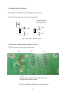
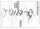
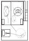
1) Solder a grounding cable to the cable shield and ground it through the
screw fixing the MAIN board. See the attached sheet.
2) Ground SC-50/110 processor unit securely.
3) Connect the cable shield at the end of the interconnected unit as below.
IEC61162-1 and AD-10 (photo coupler): Frame Ground (FG)
IEC61162-2 (RS422/485): Signal Ground (SG)
4) Connect the interconnected unit securely
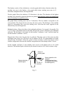
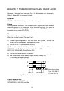
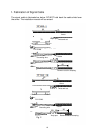
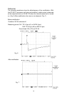
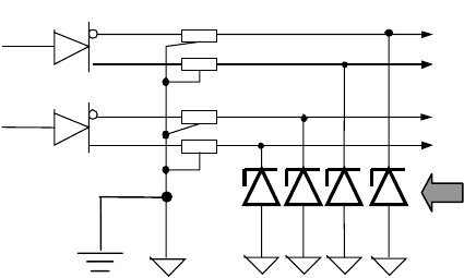
5) Add zener diodes in the heading output circuit to protect the
IC from being damaged by surge.
Fig.1 Zener diodes added in data output circuit
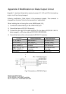
Factory-modified sets
SC-110 (SC1101): 4404-0329 and after
SC-50 (SC501): 4403-2224 and after
Zener diodes added
Type: RD9.1EB3-T4
C/N: 000
-
138
-
700