


Contents
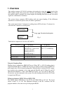
1. Overview ...................................................................................... 1
2. Maintenance Menu....................................................................... 2
1) MONITOR display ..............................................................................2
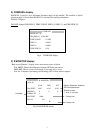
2) COMPASS display .............................................................................3
3) R MONITOR display ..........................................................................3
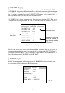
4) R-CALIB display ................................................................................4
5) RATE ERR display ............................................................................5
6) OUTPUT display ................................................................................5
7) ALARM display ..................................................................................6
8) ANALOG display ................................................................................6
9) ANT MONI display .............................................................................6
10) MESSAGE display ...........................................................................8
11) REC MONI menu .............................................................................8
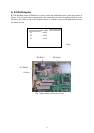
3. Replacement of Battery ................................................................ 9
4. Reading Program Number............................................................ 9
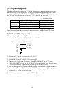
5. Program Upgrade......................................................................... 10
1) MAIN board .......................................................................................10
2) CPU board .........................................................................................11
6. Maintenance................................................................................. 12
6.1 Adjustment .......................................................................................12
6.2 Line voltage check ............................................................................12
6.3 Jumper setting....................................................................................12
6.4 LED ..................................................................................................12
7. Location of Parts........................................................................... 13
Appendix 1 Protection of ICs in Data Output Circuit......................... 15
Appendix 2 Modification on Data Output Circuit ............................... 20
Exploded View (Parts List)
Radome Antanna, C7251-E01 .................................................................D-1
Processor Unit, C7251-E02 ....................................................................D-2
Schematic Diagrams
Interconnection Diagram, C7251-C01 ....................................................S-1
Processor Unit (SC-510), C7251-K01 ....................................................S-2
POWER Board (20P8181, 1/2), C7251-K02 ..........................................S-3
POWER Board (20P8181, 2/2), C7251-K03 ..........................................S-4