


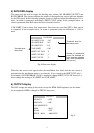
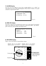
5
Number of consecutive
errors (For example, an
error message appears
with three consecutive
ROL errors.)
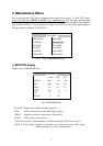
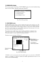
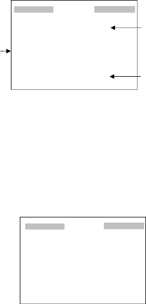
5) RATE ERR display
This menu sets the level to trigger the heading error alarms; NO HEADING OUTPUT and
RATE ERROR. The system compares the output of the angular rate sensor with one obtained
by the GPS signal. In the following example, an error is detected when the difference is 2.0º or
more. An alarm is generated according to SHIFT CONT setting. In the example below, an
alarm is generated when Roll sensor has four consecutive errors.
YAW LIMIT: Used to detect Yaw output error. Successive two yaw data (GPS + Rate sensor)
is compared. In the example below, an alarm is generated when the difference is 1.00º or
more.
Fig. 8 Rate error display
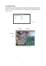
When the rate sensor error appears after the installation, first check that the rate sensor is
mounted and the installation menu is set correctly. If yes, increase the SHIFT CNT only 1.
For example, if RATE ERROR! (YAW) is displayed, change SHIFT CNT YAW from 0 to 1.
Never change the setting of WA SHIFT and YAW LIMIT.
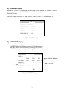
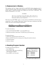
6) OUTPUT display
DO NOT change the setting in this menu, except for HDM. R&D engineers use this menu
for investigation. HDM is changed to TRUE if necessary.
Fig. 9
RATE ERR
WA SHIFT YAW : 2.0º
WA SHIFT ROL : 2.0º
WA SHIFT PIT : 2.0º
YAW LIMIT : 1.00º
SHIFT CNT YAW : 0
SHIFT CNT ROL : 3
SHIFT CNT PIT : 3
Threshold level fo
r
rate sensor error
Yaw data error
alarm level
OUTPUT
M2 DATA : OFF
GPS DATA : OFF
LOG SENTENCE?
HDM : MAG
WAAS : OFF
PITCH ROLL : ABSOLUTE