


20
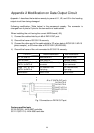
Appendix 2 Modification on Data Output Circuit
Appendix 1 describes the tentative remedy to prevent U1, U2, and U3 in the heading
output circuit from being damaged.
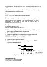
Following modification (Table below) is the permanent remedy. The connector is
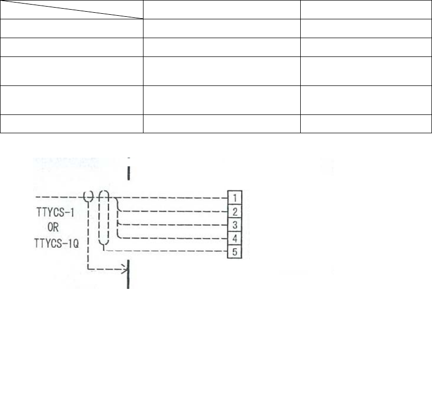
changed from 4 pins to 5 pins for the connection of cable shield.
When installing the unit having the current MAIN board (-55);
1) Connect the cable shield to pin #5 of DATA OUT port.
2) Ground the frame of SC-50/110 securely.
3) Connect the other end of the cable shield to FG when data is IEC61162-1/AD-10
(photo coupler), or SG when data is IEC61162-2 (RS422/485).
4) Ground the frame of the unit connected to SC-50/110 securely.
Before modification After modification
U1, U2, and U3 MAX3043EUE-T SN75ALS172DE
CR7 to CR30 RD9.1EB3-T4 1SS226-TE85LF
Connectors (J2 to J7),
DATA1 to DATA 6
231-334/001-000, 4-pin
connector
231-335/001-000,
5-pin connector
Plugs (P2 to P7),
DATA1 to DATA 6
231-304/026-FUR,
4-pin plug
231-305/026-FUR,
5-pin plug
MAIN board 20P8178-33 20P8178-55
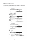
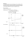
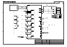
Fig.1 Connection on DATA OUT port
Factory-modified sets
SC-50 (SC501): 4403-2637 and after
SC-110 (SC1101): 4404-0360 and after
DATA-H/TD-A
DATA-C/TD-B
SHIFT-H/TD’-A
SHIFT-C/TD’-B
FG
J2 to J7 (DATA OUT port)