


10
Copyright ©2001 Liberty Group
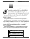
Atlas & Yukon Second Stage
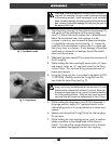
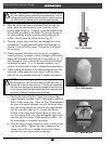
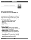
Fig. 3 – Orifice Removal
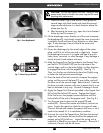
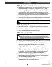
Fig. 4 – Orifice Inspection
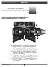
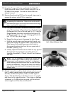
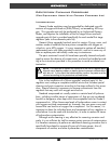
Fig. 5 – Genesis Rim Clamp
NOTE: The orifice is O-ring sealed and will remain inside
the inlet coupling after performing the above step. The fol-
lowing step must be performed correctly in order to remove
the orifice without damaging its polished sealing edge.
8. After the orifice has been unthreaded from the inlet cou-
pling, stand the inlet coupling on end with the orifice
sealing edge facing up. Carefully insert the handle of the
blunt probe (provided in the Select Kit) through the top of
the inlet coupling, directly over the sealing edge of the
orifice. Gently press the orifice out (see Fig. 3).
9. To avoid using a sharp tool that can damage the orifice,
squeeze the O-ring(4) between thumb and forefinger to
remove it from the orifice head. Discard the O-ring and
do not reuse.
10. Closely examine the orifice with the use of a magnifier,
checking for any scratches or other damage to the sealing
edge and the groove that holds the O-ring (see Fig. 4). If
any damage or wear is found, discard the orifice and do
not attempt to reuse. If it is in reusable condition, set it
aside on a soft surface to keep it isolated from metal parts.
11. While holding the bottom of the second stage secure with
one hand, firmly grasp the cover ring(1) with the other,
and turn the ring counter-clockwise to loosen and remove.
NOTE: If the cover ring cannot be removed by hand, it may
be necessary to use the Rim Clamp (PN 22-680-200), to-
gether with a bench-mounted vise. This Genesis specialty
tool has been designed to prevent damage to the cover ring
or the second stage during disassembly, but it must be used
correctly, following the steps outlined below.
a. Identify the side of the Rim Clamp that contains the
larger diameter shoulder, which is designed to hold the
Atlas/ Yukon cover ring. Place the Rim Clamp between
the jaws of a bench mounted vise with the larger diam-
eter side facing straight up, and the split edge parallel
with the vise jaws (see Fig. 5). Ensure that the top
surface of the clamp rests slightly above or flush with
the top surface of the vise jaws, and gently tighten the
vise only until the clamp is held securely in place. Do
not over-tighten or compress the clamp.
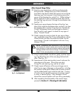
b. Place the second stage inside the clamp, with the cover
ring facing down. Tighten the vise to compress the
clamp, only as far as is needed to secure the clamp
around the cover ring to prevent slippage.