


26
Copyright ©2001 Liberty Group
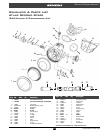
Atlas & Yukon Second Stage
Fig. 15 – Pop p et Installation
Fig. 16 – Locknut Installation
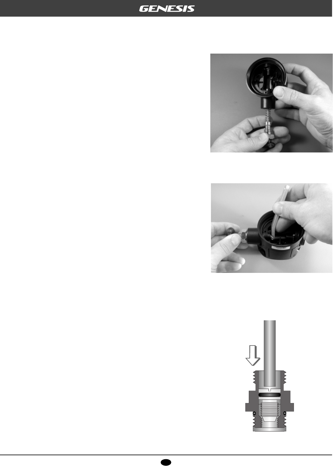
Fig. 17 – Orifice Installation
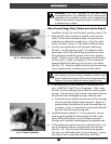
7. Fit the LP seat(8) into the head of the poppet(9) with the
smooth side facing out. Ensure that it is seated flush with
the inner rim of the poppet. DO NOT use adhesive.
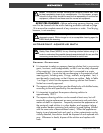
8. Stand the Poppet Drive Tool (provided in the Genesis
Poppet Tool Kit – PN 20-640-100) on its knob, with the
drive socket facing straight up. Index the tabs of the
poppet head with the driver, and stand the poppet inside
the tool with the shaft facing straight up.
9. Apply a light coat of lubricant to both ends of the poppet
spring(10), and place the spring over the poppet shaft.
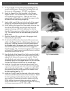
10. While holding the Poppet Drive Tool stable, mate the inlet
tube of the second stage case straight down over the
poppet and spring, and hold it depressed so that the
threads of the poppet are visible inside the case (see Fig.
15). Turn the hex nut of the tool clockwise by hand until
lightly snug.
11. Place the washer(22) over the end of the poppet shaft,
followed by the spacer(20).
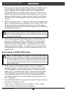
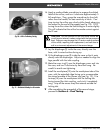
12. Fit the locknut(19) into the closed end of the wrench pro-
vided in the Poppet Tool Kit, with the larger diameter end
facing out. Hold the wrench with the nut mated against
the threaded end of the poppet shaft, and slowly turn the
knob of the Poppet Drive Tool clockwise to engage the
threads (see Fig. 16). Continue turning the knob clockwise
until exactly 3 threads extend outside the locknut, and then
remove the wrench from the nut.
13. Press the knob of the Poppet Drive Tool inward and hold it
fully depressed to insert the arms of the lever(21) over the
poppet shaft, between the spacer and washer. Slowly
relax the knob, and watch to ensure that the lever stands
completely upright as the poppet retracts into the inlet tube.
Unscrew and remove the tool from the second stage.
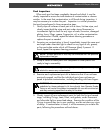
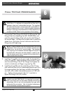
14. Install the O-ring(4) onto the head of the orifice(5), and
insert the orifice into the open end of the inlet coupling(6)
with the threaded end facing in. Apply the handle of the
blunt probe to seat the orifice against the threads inside
the inlet coupling (see Fig. 17).
15. Install the O-ring(7) onto the short end of the inlet coupling,
at the base of the threads closest to the hex feature. Mate
the inlet coupling into the inlet tube of the second stage
case, and turn it clockwise by hand to tighten until snug.
While holding the second stage case secure, apply a
torque wrench with a w” hex socket to tighten the coupling
to a torque measurement of 90 (±5) inch-lbs.