


25
Copyright ©2001 Liberty Group
Service & Repair Manual
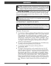
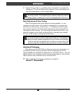
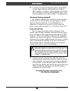
Fig. 13 – Atlas Retaining Ring Installation
WARNING: DO NOT attempt to use any other
manufacturer’s part as a substitute for any Genesis part,
regardless of any similarity in shape, size, or appearance.
Doing so may render the product unsafe, and could result
in serious injury or death.
Atlas Second Stage Only (Yukon proceed to Step 5)
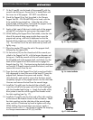
1. Install the O-ring(11b) onto the dive/ pre-dive switch(11c).
2. Mate the flat vane of the dive/ pre-dive switch into the
case(11) above the mouthpiece tube, and position the
indicator pin above the curved recess. Press the switch
firmly into place so that it is fully seated inside the case.
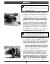
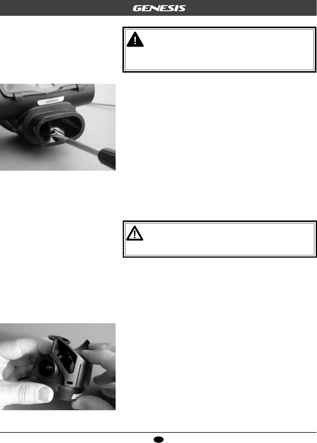
3. Turn the case upside down with the open side facing
forward. Lay the retaining ring(11a) inside the mouth-
piece tube, with its flat side facing up and the two ends
facing directly toward the groove of the dive/ pre-dive
switch. Check to ensure that the groove around the base
of the switch is visible, and apply a 3.5mm screwdriver
squarely behind the retaining ring to press it into place
(see Fig. 13). Examine closely to ensure that the retaining
ring is seated evenly inside the groove of the switch.
CAUTION: It is important to ensure that the switch, O-ring,
and retaining ring are correctly installed in order to main-
tain the watertight integrity of the second stage assembly.
Failure to do so may cause the second stage to flood.
4. If the case plug(16) was removed for replacement with
new, install the O-ring(17) onto the groove. Then, mate
the stem into the case opening and flex the retaining tabs
inward. Press the plug firmly inward, and check to ensure
that all three tabs are seated securely inside the case.
a. Fit the retaining ring(18) over the stem of the case plug
with the retaining spokes angled upward. Apply two
medium blade screwdrivers to press the retaining ring
into place, until it is seated secure and evenly between
the stem and all three retaining tabs.
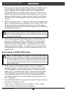
5. Install the exhaust valve(15), if it was removed, into the
case by gently pulling the stem through the hole in the
center of the sealing area, until the barb has passed
through and is securely seated against the opposite side.
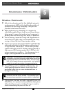
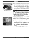
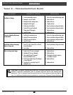
6. Fit the exhaust tee against the case, so that the slots in the
top of the exhaust tee are resting directly over the tabs
(see Fig. 14). Snap the top of the exhaust tee together
with the case, followed by the two lower flanges. Ensure
that all four tabs are securely locked into their slots.
Fig. 14 – Exhaust Tee Installation