


Repair
312497G 13
Locating and Repairing
Blockages
Blocks will cause a higher than normal pumping pres-
sure. Depending on the application or system design,
this blockage will usually result in a complete loss of
lubricant flow into the total system and no bearing will be
receiving lubrication.
The loss of flow due to a blockage is first indicated with
the higher than normal system pressure that is devel-
oped by the pump as it attempts to overcome this block-
age. Higher pressure is limited, isolated and signaled
through the use of various performance indicators, reset
and relief, incorporated into the system design.
Performance Indicators
Performance indicators are pressure-sensitive devices
that pinpoint excessive pressure in the lubricating sys-
tem.
These devices are installed in the indicator ports of
divider valves, signal a fault either by causing an indica-
tor pin to protrude or by releasing lubricant into the
atmosphere.
NOTE: Never block a lube outlet that is designed to dis-
charge lubricant.
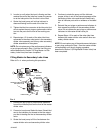
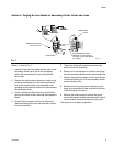
Reset Indicator with Memory
Reset indicators stop lube system operation when a
fault occurs. These devices can be used in either master
or secondary divider valves.
When a lube line becomes blocked, the resultant high
pressure pushes the indicator pin through the opening in
the cap. The high pressure prevents the affected divider
valve piston from completing its cycle, causing a pres-
sure backup through the divider valve which trips a pres-
sure switch upstream from the valve and shuts off the
pump.
The indicator pin remains extended until it is reset man-
ually. This helps locate the lube line that is blocked.
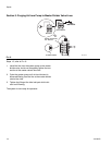
Rupture Indicator
Rupture indicators are used on MSP/MH divider valve
applications where lube system pressure exceed 2500
psi. The high pressure from the lube line blockage
causes a disc to rupture. The lubricant then forces an
indicator to protrude, locating the blockage. The high
pressure backs up through the system and trips a switch
to shut the system off. When the fault is corrected, the
disc must be replaced and the pin reset manually.
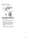
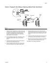
Automatic Relief Indicator
An automatic relief indicator pinpoints lube line blockage
but allows the lube system to continue supplying lubri-
cant to points that are not blocked. They are used pri-
marily in secondary divider valves. The excessive
pressure created by line blockage moves a piston,
enabling the lubricant to escape through a vent. When
the pressure is relieved, the spring resets the piston.
Because these devices permit the lube system to keep
operating when a lube point is blocked, a separate pres-
sure switch connected to an audible alarm should be
used to warn of high pressure.
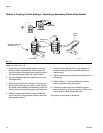
Locating and Repairing Blockages
1. Make a visual inspection of the system. Check for
crushed lines or improper divider valve installation.
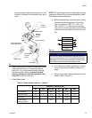
2. Verify that each divider valve outlet required to dis-
charge lubricant can do so and that no pipe plugs
have been installed in an outlet designed to serve a
bearing or another divider valve.
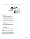
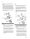
3. Use a manual pump with a gauge. Fill the pump with
clean, filtered lubricant. Connect the manual pump
to the inlet of the master divider valve and slowly
operate pump. If system will not cycle freely, below
1500 psi, see Master Divider Valve Equipped with
Performance Indicator [Step 4a (below)].
NOTE: Use only clean oil filtered to the SAE -recom-
mended cleanliness level of ISO 18/14 (ISO Standard
4406) when prefilling a system. The manufacturers of
the machine tool and its component bearings should be
consulted to ensure that the ISO 18/14 cleanliness level
is adequate.