


Repair
14 312497G
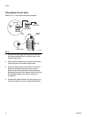
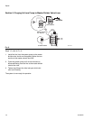
4a. Master Divider Valve Equipped With Performance
Indicator
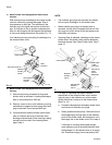
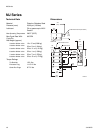
With manual pump connected to the master divider
valve as outlined in Locating Blockages, Step 3,
raise pressure to 2000 psi. The indicators in the
indicator ports will signal the location of the block-
age. An indicator in the up position indicates pres-
sure is in that outgoing line and signals the blockage
is in the area being served from this outlet (F
IG. 11).
If no indicator pins are protruding, the blockage is in
the master divider valve.
4b. Master Divider Valve Equipped Without Performance
Indicator
1) With manual pump connected to the master
divider valve as outlined in Locating Blockages,
Step 3, raise pressure to 2000 psi.
2) Remove, one at a time, each indicator port plug
and attempt to operate manual pump after each
plug is removed. Do not exceed 2000 psi.
3) If pressure drops and the master cycles freely
after an indicator port plug is removed, then
blockage is downstream in the area that is being
served from that outlet. See Locating Block-
ages, Step 3.
NOTE:
• If all indicator port plugs are removed, the master
will not cycle. Blockage is in this divider valve.
• When indicator port plug of a blocked area is
removed, a small shot of trapped lubricant will usu-
ally surge out of this outlet as the inlet pressure on
the divider valve drops.
• If testing (Step 4) indicates a blockage in the master
divider valve, this divider valve must be disassem-
bled and cleaned. See Clean Divider Valve, Step 7,
page 15.
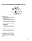
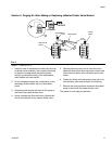
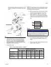
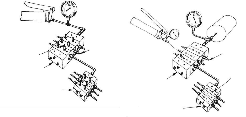
5. If in Step 4, a blockage has been indicated
downstream of the master divider valve, install a
manual pump in the indicator port of the master
divider valve that is common to the blocked area.
(See F
IG. 12).
a. Proceed to downstream secondary divider valve
and remove all indicator port plugs.
b. Slowly operate manual pump. If lubricant can be
discharged freely through each of the indicator
ports of this divider valve, the blockage is not in
the supply line or the divider valve. Go to step 6.
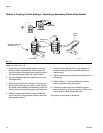
If lubricant is not freely discharged through
open indicator ports of the second divider valve,
the blockage is in this divider valve or its supply
line. Disconnect supply line at secondary inlet
FIG. 11
HAND PUMP
LUBE
INDICATOR PIN UP
MASTER
SECONDARY
OUTLETS
DIVDER
VALVE
DIVIDER
VALVE
TI11103
FIG. 12
TI11104
HAND PUMP
SYSTEM PUMP
MASTER
DIVDER
VALVE
SECONDARY
DIVIDER
VALVE
LUBE
OUTLETS
INDICATOR
PORT
PLUGS
REMOVED