


Set Up
312964C 3
Set Up
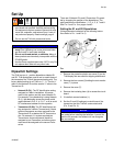
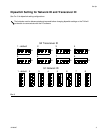
Dipswitch Settings
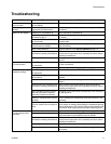
The TLM has two, 4 - position dipswitches labeled S1
and S2. TLM dipswitches must be set to match those of
the transceiver the TLM will be communicating with. The
factory default setting for all TLM’s is (‘1’ ‘1’). The first ‘1’
refers to the Network ID and the second ‘1’ refers to the
Transceiver ID.
• Network ID (S1): The RF identification setting
assigned to a Matrix installation. All compo-
nents in the system use this same Network ID.
For example, if one dealership is using Network
ID (1), the dealership across the street would
require Network ID (2, 3, 4, 5, 6, 7, or 8) to avoid
RF interference between the two systems.
• Transceiver ID (S2): The RF identification set-
ting assigned to a Matrix Transceiver(s). Matrix
system components are then assigned to the
Transceiver’s ID as desired for RF communica-
tion. For example, if a system required two
Transceivers, some components would be
assigned to one Transceiver and other compo-
nents would be assigned to the second Trans-
ceiver.
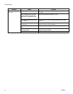
There are 8 Network ID's and 8 Transceiver ID's possi-
ble by changing the position of the dipswitches. The
eight positions are identified as 1, 2, 3, 4, 5, 6, 7 and 8.
See F
IG. 2 and FIG. 3 on pages 4 and 5.
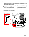
Setting the S1 and S2 Dipswitches
(Unless otherwise indicated, for the following instruc-
tions Refer to F
IG. 1 and FIG. 2)
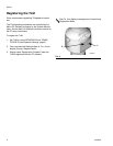
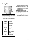
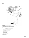
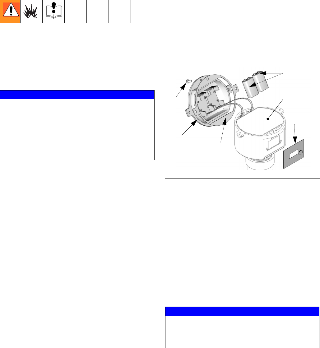
1. Remove the protective plastic over cover (5) on the
TLM display that was used for shipping and discard.
2. Remove the four screws (3) holding the tank monitor
cover (7) in place.
3. Remove the cover (7).
4. Remove the insulating foam (4) to access the circuit
board.
5. If installed, remove batteries (1).
6. Set the S1 and S2 settings to match those of the
transceiver that this TLM will communicate with
(F
IG. 2 and FIG. 3).
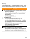
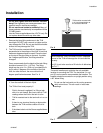
• Do not install or service this equipment unless you
are trained and qualified. Installing and servicing
this equipment requires access to parts which may
cause fire, explosion, and serious injury if work is
not performed properly. Read warnings, page 2.
• Do not use the TLM with pressurized tanks.
NOTICE
• Do not over tighten tank level monitor into tank
bung! Over tightening can cause permanent dam-
age and result in inaccurate readings.
• Do not use thread sealant or adhesive. Many of
these products are chemically incompatible with the
PC/ABS plastic.
• Use the Graco-supplied down tube 15U731 only. Do
not replace down tube with any other tube.
FIG. 1
NOTICE
Wait at least 30 seconds after the dipswitch settings
are made before installing the batteries. If you do not
wait the 30 seconds, the software will not recognize
the new settings.
3
2
1
4
5
7