


14 308639
Service
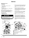
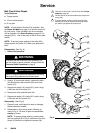
Ball Check Valve Repair
Tools Required
D Torque wrench
D 15-mm socket wrench
D O-ring pick
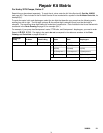
NOTE: A Fluid Section Service Kit is available. See
the Repair Kit Matrix on page 21 to find the correct kit
for your pump. Parts included in the kit are marked
with an asterisk in the Parts Drawing on page 22, for
example (201*). Use all the parts in the kit for the best
results.
NOTE: To ensure proper seating of the balls (201),
always replace the seats (101) when you replace the
balls.
Disassembly (See Fig. 6)
1. Relieve the pressure.
WARNING
To reduce the risk of serious injury whenever you
are instructed to relieve pressure, always follow the
Pressure Relief Procedure on page 9.
WARNING
Some of the pump parts and assemblies are heavy.
Use proper lifting equipment and techniques.
2. Using a 15-mm socket wrench, remove the bolts
(54) holding the outlet manifold (50) to the fluid
covers (51).
3. Remove the seats (101), balls (201), and o-rings
(102) from the fluid covers (51).
4. Remove the inlet manifold bolts (54).
5. Remove the seats (101), balls (201), and o-rings
(102) from the fluid covers (51).
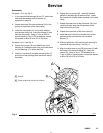
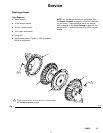
Reassembly (See Fig. 6)
1. Clean all parts, and inspect for wear or damage.
Replace parts as needed.
2. Reassemble in the reverse order, following all
notes in Fig. 6. Be sure all parts are assembled
exactly as shown.
NOTE: To ensure proper seating, visually check
that the manifold (50 or 53) is centered on the fluid
covers (51) before you tighten the screws (54).
Torque to 55 to 60 ft-lb (75 to 81 NSm). See Torque
Sequence, page 25.
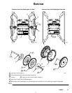
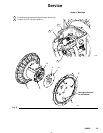
Fig. 6
1
2
The ball seat is on the same side as the step for the
o-ring (102).
06325
50
51
54
54
102
101
102
201
201
53
1
1
2
101
2
3
To ensure proper seating, visually check that the
manifold (50 or 53) is centered on the fluid covers
(51) before you tighten the screws (54).
3
3