


7
7308639
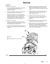
Installation
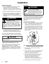
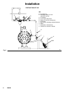
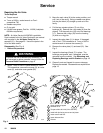
Changing Manifold Orientation
(See Fig. 6 on page 14)
The outlet manifold (50) and inlet manifold (53) can be
rotated to best suit your installation needs. The pump
is shipped with the inlet and outlet facing in the same
direction.
1. Remove the screws (54) from each end of the
manifold (50 or 53).
2. Turn the manifold to the desired position, and
reinstall the screws (54). Torque to 55 to 60 ft-lb
(75 to 81 NSm). See Torque Sequence, page 25.
NOTE: To ensure proper seating, visually check
that the manifold is centered on the fluid covers
(51) before you tighten the screws (54).
Fluid Pressure Relief Valve
Some systems may require installation of a pres-
sure relief capability at the pump outlet to prevent
overpressurization and rupture of the pump or
hose.
Thermal expansion of fluid in the outlet line can
cause overpressurization if the fluid line is close
ended. Such overpressurization can occur when
using long fluid lines exposed to sunlight or ambi-
ent heat, or when pumping from a cool to a warm
area (for example, from an underground tank).
CAUTION
Air Exhaust Ventilation
WARNING
TOXIC FLUID HAZARD
Be sure to read and follow the USING
HAZARDOUS FLUIDS, and FIRE OR
EXPLOSION HAZARD warnings on
page 3, before you operate this pump.
Be sure the system is properly ventilated
for your type of installation. You must
vent the exhaust to a safe place, away
from people, animals or food handling
areas when pumping flammable or
hazardous fluids.
The minimum size for the air exhaust hose is1 in.
(25.4 mm) ID x 5 ft. (1.5 m). If a longer hose is
required, use a larger diameter hose. Avoid sharp
bends or kinks in the hose.
If the diaphragm ruptures, the fluid being pumped
will be exhausted with the air. Place a container at
the end of the air exhaust line to catch fluid in case
the diaphragm ruptures.
The air exhaust port is 1 npt(f). Do not restrict the air
exhaust port. Excessive exhaust restriction can cause
erratic pump operation.
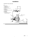
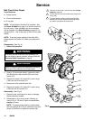
To provide a remote exhaust:
1. Remove the muffler (60) from the pump air
exhaust port.
2. Install a grounded air exhaust hose (T) and
connect the muffler (60) to the other end of the
hose. The minimum size for the air exhaust hose
is 1 in. (25.4 mm) ID x 5 ft (1.5 m). If a longer
hose is required, use a larger diameter hose.
Avoid sharp bends or kinks in the hose. See
Fig. 3.
3. Place a container (U) at the end of the air exhaust
line to catch fluid in case a diaphragm ruptures.