


16 308639
Service
Disassembly
1. Relieve the pressure.
WARNING
To reduce the risk of serious injury whenever you
are instructed to relieve pressure, always follow the
Pressure Relief Procedure on page 9.
WARNING
Some of the pump parts and assemblies are heavy.
Use proper lifting equipment and techniques.
2. Remove the manifolds and disassemble the ball
check valves as explained in Ball Check Valve
Repair on page 14.
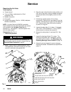
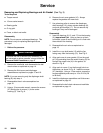
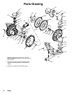
3. Using a 15-mm socket wrench, remove the
screws (54), and pull the fluid covers off the pump.
See Fig. 7.
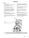
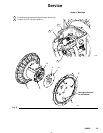
For steps 4 to 9, see Fig. 8.
4. Using 15/16-in. wrenches or sockets, loosen but
do not remove one of the diaphragm plate bolts
(62). (whichever one turns)
5. Remove the fluid-side plate (52), diaphragm (301),
and air-side plate (57).
For models with PTFE diaphragms, also remove
the shim (302) and back-up diaphragm (303).
6. Pull the other diaphragm assembly and the
diaphragm shaft (14) out of the center housing (2).
Hold the shaft flats with a 7/8-in. wrench, and
remove the remaining fluid-side plate (52) from the
shaft. Disassemble the remaining diaphragm
assembly.
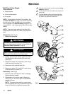
7. Inspect the diaphragm shaft (14) for wear or
scratches. If it is damaged, inspect the bearings
(13) in place. If the bearings are damaged, see
Removing and Replacing Bearings and Air
Gasket on page 18.
8. Reach into the center housing (2) with an o-ring
pick, and hook the u-cup seals (15), then pull them
out of the housing. This can be done with the
bearings (13) in place.
9. Clean all parts and inspect for wear or damage.
Replace parts as needed.
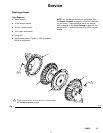
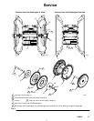
Reassembly (See Fig. 8)
1. Install each u-cup seal (15) so the lips face away
from the center of the pump. Lubricate the u-cup
seals.
2. Install a diaphragm assembly on one end of the
shaft (14) as follows:
a. Place a washer (63) and then a white o-ring
(64) on the diaphragm bolt (62). The o-ring
may fit very snugly on the bolt. Insert the bolt
into the fluid-side diaphragm plate (52) as
shown in Fig. 8. Grease the bolt threads.
b. Lay the diaphragm (301) into the grooves on
the fluid-side diaphragm plate (52) so that the
side marked AIR SIDE faces the center of the
pump.
For models with bolt–through PTFE
diaphragms, also install the shim (302) and
back-up diaphragm (303), as shown in Fig. 8.
Line up diaphragm tabs with tabs on air cover.
The bolts must go through the bolt–through
PTFE diaphragm.
c. Place the air-side diaphragm plate (57) and
washer (63) over the bolt. Screw the shaft
(14) onto the bolt handtight.
3. Grease the length of the shaft (14), and slide it
through the center housing (2).
4. Assemble the other diaphragm assembly to the
shaft as explained in step 2.
Step 5 is easiest if the pump is mounted vertically in a
vise.
5. Torque the bolts (62) to 100 to 120 ft-lb (136 to
163 NSm).
WARNING
Failure to properly torque the diaphragm bolts (62)
could result in a bolt failure. If a diaphragm bolt
fails, fluid is exhausted through the muffler. See
Air Exhaust Ventilation on page 7.
6. Install the fluid cover screws (54) hand tight.
Torque the screws to 55 to 60 ft-lb (75 to 81 NSm)
in a crossing pattern. See Fig. 7. See Torque
Sequence, page 25.
7. Reassemble the ball check valves and manifolds
as explained on page 14.