


6 308639
Installation
Mountings
CAUTION
The pump exhaust air may contain contaminants.
Ventilate to a remote area if contaminants could
affect your fluid supply. See Air Exhaust Ventila-
tion on page 7.
D Be sure the mounting can support the weight of the
pump, hoses, and accessories, as well as the
stress caused during operation.
D For all mountings, be sure the pump is secured with
screws through the mounting feet (58). See the
mounting feet in the Parts Drawing on page 22.
Air Line
WARNING
A bleed-type master air valve and a fluid drain
valve are required on your system.
The bleed-type master air valve relieves air
trapped between itself and the pump. Trapped air
can cause the pump to cycle unexpectedly, which
could result in serious bodily injury, including
splashing in the eyes, injury from moving parts, or
contamination from hazardous fluids.
The fluid drain valve reduces the risk of serious
bodily injury, including splashing in the eyes or on
the skin, or contamination from hazardous fluids.
Install the fluid drain valve close to the pump’s
fluid outlet to relieve pressure in the hose if the
hose becomes plugged.
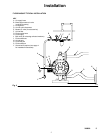
1. Mount the air line accessories on the wall or on a
bracket. Be sure the air line supplying the
accessories is grounded.
a. The pump speed can be controlled in one of
two ways: To control it on the air side, install
an air regulator. To control it on the fluid side,
install a fluid valve near the outlet.
b. Install a bleed-type master air valve
downstream from the air regulator, and use it
to relieve trapped air. See the WARNING,
above. Locate another bleed-type master air
valve upstream from all air line accessories,
and use it to isolate the accessories during
cleaning and repair.
c. The air line filter removes harmful dirt and
moisture from the compressed air supply.
2. Install a flexible air hose between the accessories
and the pump air inlet. Screw the air line fitting
into the air inlet.
3. Do not restrict the exhaust port. Excessive
exhaust restriction can cause erratic pump
operation.
Fluid Lines
WARNING
Graco always recommends that you use grounded
fluid hoses to dissipate static electricity. When
pumping non-conductive flammable fluids, groun-
ded fluid hoses are required. See Fire and Explo-
sion Hazard on page 3.
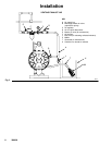
Fluid Outlet Line
1. Attach the fluid outlet hose to the fluid outlet flange
by using a 3-in. ANSI or DIN flanged hose or pipe.
2. Install a fluid drain valve near the fluid outlet. See
the WARNING in the Air Line section at left.
Fluid Suction Line
Attach the fluid suction hose to the pump fluid inlet
flange by using a 3-in. ANSI or DIN flanged fluid
suction hose or pipe.
D If the inlet pressure to the pump is more than 25
percent of the outlet working pressure, the ball
check valves do not close fast enough, which
results in inefficient pump operation.
D At inlet fluid pressures over 15 psi (100 kPa, 1.0
bar), diaphragm life is shortened.
D The maximum suction lift is 8 ft (2.5 m) of water dry
or 28 ft (8.5 m) of water wet. For suction lifts
between 8 ft (2.5 m) and 28 ft (8.5 m) of water, it is
necessary to install a foot valve, and it is necessary
to flood the suction to prime the pump. The pump
may prime better if you reduce the inlet air pressure
until the pump is primed.