


18 308639
Service
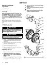
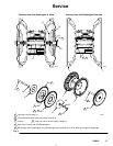
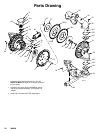
Removing and Replacing Bearings and Air Gasket (See Fig. 9)
Tools Required
D Torque wrench
D 13-mm socket wrench
D Bearing puller
D O-ring pick
D Press, or block and mallet
Disassembly
NOTE: Do not remove undamaged bearings. This
procedure is only for replacing bearings that are
damaged.
1. Relieve the pressure.
WARNING
To reduce the risk of serious injury whenever you
are instructed to relieve pressure, always follow the
Pressure Relief Procedure on page 9.
2. Remove the manifolds, and disassemble the ball
check valves as explained on page 14.
3. Remove the fluid covers and diaphragm
assemblies as explained on pages 15 and 16.
NOTE: If you are removing only the diaphragm shaft
bearing (8), skip step 4.
4. Disassemble the air valve as explained on
page 12.
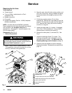
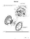
5. Using a 13-mm socket wrench, remove the screws
(27) holding the air covers (1) to the center
housing (2). See Fig. 9.
6. Remove the air cover gaskets (10). Always
replace the gaskets with new ones.
7. Use a bearing puller to remove the diaphragm
shaft bearings (13), piston actuator bearings (8),
and push pin bearings (17). Do not remove any
bearings if they are not damaged.
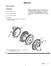
Reassembly
1. Insert the bearings (8, 13, and 17) into the housing
(2), tapered end first. Using a press or a block
and mallet, press-fit each bearing so it is flush with
the surface of the housing.
2. Reassemble the air valve as explained on
page 13.
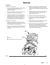
3. Install the u-cup shaft seals (15) with the lips
facing away from the bearing (13). See Fig. 8.
4. Align each new air cover gasket (10) so the push
pin (18) protruding from the center housing (2) fits
through the proper hole (H) in the gasket, as
shown in Fig. 8.
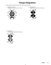
5. Align each air cover (1) so the through hole is on
the bottom, as shown in Fig. 8. Install the screws
(27) handtight. Using a 13-mm socket, torque the
screws oppositely and evenly to 19 to 21 ft-lb (26
to 28 NSm).
6. Install the diaphragm assemblies and fluid covers
as explained on page 16.
7. Reassemble the ball check valves and manifolds
as explained on page 14.