


18
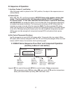
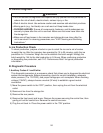
3. Shutdown
2. Freeze Cycle
Bin Full
Power Switch
"ON"
BC open
BCH continues
Comp de-energized
FM de-energized
GM de-energized
WV de-energized
BC closed
BC closed
LF/S closed
UF/S closed
BCH continues
Comp energized
FM energized
GM energized
WV de-energized
BC closed
UF/S open
LF/S open
FT starts (90 sec.)
BCH continues
Comp continues
FM continues
GM continues
WV energized
BC closed
UF/S open
LF/S open
BCH energized
WV energized
1. Fill Cycle
BC closed
LF/S closed
UF/S closed
FT terminated
BCH continues
Comp continues
FM continues
GM continues
WV de-energized
Low Water Safety
BC closed
UF/S open
FT exceeded
BCH continues
WV continues
Comp de-energized
FM de-energized
GM de-energized
Rell
FT (in TDR)
Maximum 90 seconds
When UF/S closes,
icemaker restarts at
2. Freeze Cycle.
90 seconds
FT
exceeded
BC
open
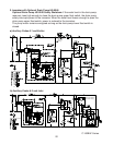
2. Auxiliary Codes A-2 and Later
After the power switch is placed in the "ON" position, the steps in the sequence are as
outlined below.
a) Fill Cycle
LF/S and UF/S open, BCH and WV energize. LF/S closes. Nothing happens at this time.
Reservoir continues to ll until UF/S closes.
b) Freeze Cycle
UF/S closes. BCH remains energized. WCR, TDR, GM, FM, CR, and Comp energize. WV
de-energizes. Ice production starts 4 to 6minutes after Comp energizes depending on
ambient and water conditions. F/S controls WV to rell as needed during the freeze cycle.
The freeze cycle continues until BC shuts down the icemaker or power is turned off to
the icemaker. Rell: As ice is produced, the water level in the reservoir drops and UF/S
opens. When UF/S opens, a latching circuit through LF/S and WCR keeps WCR, TDR,
GM, FM, CR, and Comp energized. When LF/S opens, WCR de-energizes, cutting power
to TDR terminal #5 (O wire) and starting FT. WV energizes. Water lls the reservoir, UF/S
closes. WCR energizes, restoring power to TDR terminal #5 (O wire) and resetting FT.
WV de-energizes. If UF/S remains open longer than 90 seconds, FT terminates, cutting
power to TDR terminal#9 (R wire). GM, FM, CR, and Comp de-energize. WV remains
energized until UF/S closes.
c) Bin Control Thermostat Shutdown
Ice lls storage bin to level of BC. BC opens within 10 seconds after ice contact. When
BC opens, BCH remains energized. WCR, TDR, GM, FM, CR, and Comp de-energize.
When ice level lowers and BC closes, the icemaker starts operating again.
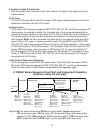
C-100BAF Series Sequence Flow Chart and Component Operation
(auxiliary codes A-2 and later)
Legend: BC–bin control thermostat; BCH–bin control heater; Comp–compressor;
CR–compressor relay; FM–fan motor; FT–90-second ll timer (low water safety;
internal to TDR); GM–gear motor; LF/S–lower oat switch; TDR–time delay relay;
UF/S–upper oat switch; WCR–water control relay; WV–inlet water valve