


26
2. Auxiliary Codes A-2 and Later
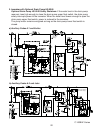
This diagnostic procedure is a sequence check that allows you to diagnose the electrical
system and components. Before proceeding, check for correct installation, adequate
water pressure (7 to 113PSIG), and proper voltage per unit nameplate. When checking
voltage (115VAC), always choose a neutral (W wire) to establish a good neutral
connection.
1) Move the power switch to the "OFF" position, then unplug the unit from the electrical
outlet.
2) Remove all ice from the storage bin.
3) Remove the rear panels.
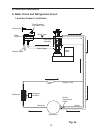
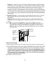
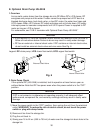
4) Remove the clamp securing the drain plug, then lower the drain hose into a container.
Remove the drain plug to drain the water from the evaporator assembly and reservoir.
See Fig. 4.
5) After all of the water has drained, replace the drain hose, drain plug, and drain clamp in
their correct positions.
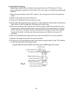
6) Remove the front panel and louver. Remove the screws securing the control box, then
gently pull out the control box. Remove the control box cover.
7) Plug the unit back in. Place the power switch in the "ON" position.
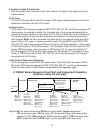
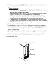
8) Fill Cycle – LF/S and UF/S open, BCH and WV energize. LF/S closes. Nothing
happens at this time. Reservoir continues to ll until UF/S closes.
Diagnosis: Check that WV lls the reservoir. If not, check water supply line shut-off
valve, water lters, WV screen, power switch, and BC assembly. See "IV.C. Bin Control
Check." Check 115VAC to WV. Check WCR terminal #2 (GY wire) to a neutral (Wwire)
for 115VAC. If 115VAC is not present, WCR is either energized or bad. If WCR is
energized, check F/S. See "IV.D.1. Float Switch Check." If 115VAC is present, check
for continuity through WV solenoid. If open, replace WV. Check that UF/S closes when
reservoir is full. If not, check F/S. See "IV.D.1. Float Switch Check."
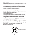
9) Freeze Cycle – UF/S closes. BCH remains energized. WCR, TDR, GM, FM, CR, and
Comp energize. WV de-energizes. Ice production starts 4 to 6minutes after Comp
energizes depending on ambient and water conditions.
Diagnosis:Check that WCR, TDR, GM, FM, CR, and Comp energize and WV
de-energizes. If not, check WCR, TDR, GM external protector, GM windings (check
when GM is cool), GM capacitor, voltage to FM, FMwindings, fan blade binding,
voltage on CR, PTC relay, voltage on Comp external protector, Comp terminals, Comp
windings, and WV. If optional drain pump HS-0248 is installed, see "IV.E. Optional Drain
Pump HS-0248." If GM starts, but the auger does not turn, check the spline coupling
between the auger and GM.
10) Rell/Low Water Safety – As ice is produced, the water level in the reservoir drops
and UF/S opens. When UF/S opens, a latching circuit through LF/S and WCR keeps
WCR, TDR, GM, FM, CR, and Comp energized. When LF/S opens, WCR de-energizes,
cutting power to TDR terminal #5 (O wire) and starting FT. WV energizes. Water lls the
reservoir, UF/S closes. WCR energizes, restoring power to TDR terminal #5 (O wire)
and resetting FT. WV de-energizes. If UF/S remains open longer than 90 seconds,
FT terminates, cutting power to TDR terminal#9 (R wire). GM, FM, CR, and Comp
de-energize. WV remains energized until UF/S closes.