


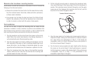

NOTE: On fiberglass hulls, it is best to start with a smaller drill bit and use progressively
larger drill bits to reduce the chance of chipping or flaking the outer coating.
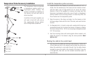
2. All mounting screws not specified require a 9/64” (3.5 mm) pilot
hole drilled approximately 5/8” (16 mm) deep. Additionally, seal any
hole drilled in the transom of the boat with marine-grade silicone
sealant (not included).
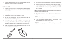
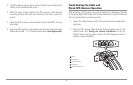
3. Route the cable to the Control Head, and insert the connector into
the appropriate slot. Use the connector designated for accessories
on the control head.
NOTE: The speed accessory will be detected only if the paddlewheel has moved
since your 900 Series™ was powered up.
4. If the connections are correct, the Control Head will begin displaying
water temperature information immediately (assuming that the
control head is powered on). If the gauge fails to read properly at
high speeds, adjust the height of the sensor on the transom.
Testing the System Installation
After you have completed the installation of the control head, transducer, and
any other accessories such as the GPS receiver, and have made all the cabling
connections required, you must test the installation before using the system.
Thorough testing should be performed with the boat in the water; however, you
can confirm basic operation initially with the boat out of the water as well.
To test the installation:
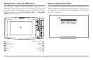
1. Press the POWER/LIGHT key on the control head once to turn on the
control head. (There will be an audible chirp to let you know that you
pressed the key, and the initial Title screen will appear.) If the unit does
not power up, make sure that power is available. While the Title screen
is shown on the display, press the MENU key to display the Start-Up
Options menu. Use the UP or DOWN 4-WAY Cursor keys to position the
cursor, then the RIGHT Cursor key to select System Status from the
Start-Up Options menu (see the Start-Up Options Menu section for
more information about these menu choices). The System Status Self
Test screen will appear.
NOTE: If you wait too long, the system will default to whichever menu mode
happens to be highlighted, and you will have to start again.
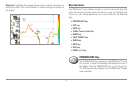
2. Self Test displays results from the internal diagnostic self test,
including unit serial number, Printed Circuit Board (PCB) serial
number, software revision, total hours of operation and the input
voltage. See System Status for more information about the Self Test.
3. From the System Status screen, view accessory connections by
pressing the VIEW key. See System Status for more information
about the Accessory Test.
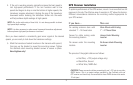
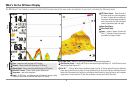
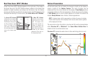
4. From the System Status screen, see a GPS Diagnostic View by pressing
the View key. GPS Diagnostic View shows a sky chart and numerical
data from the GPS receiver. The sky chart shows the location of each
visible GPS satellite with its satellite number and a signal strength bar.
A dark grey bar indicates that the satellite is being used to determine
your current position. A light gray bar indicates that the satellite is
being monitored, but is not yet being used. See System Status for
more information about the GPS Diagnostic View.
26