


MX535 UAIS Transponder Unit
Technical & Installation Manual
____________________________________________________________________________________________
www.mx-marine.com
6
3 Installation .
3.1 General Requirements
Please note that international conventions, regulations, instructions and guidelines have to be adhered to when
installing the MX535 AIS transponder.
The following points must be observed before installation can commence:
• Trained service personnel must undertake the installation.
• The MX535 Transponder must be fitted in a suitable place on the bridge.
• The VHF and GPS Antennas must be installed in a suitable position, where excellent reception conditions
apply (refer to Section 3.5, Installation of VHF and GPS antennas – page 21)
• All available interfaces must be installed.
• The vessels power supply must suffice, and the GMDSS power supply has to be used.
• Installation of the pilot plug in conning position (close to the pilot working place).
3.2 Installation Overview
3.2.1 Survey
AIS is considered part of the ship’s radio station and is surveyed together with radio installation. Surveys on
SOLAS Convention ships should be carried out in accordance with the rules laid down in IMO Res. A 746(18)
"Survey Guidelines under the harmonised system of survey and certification" (R) 8, and "Protocol of 1988
relating to the International Convention for the Safety of Life at Sea, 1974."
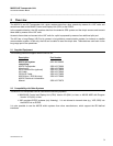
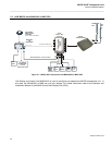
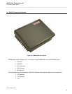
The MX535 system consists of the MX535 Transponder Unit, MX420 CDU, VHF Antenna, Backup GPS
Antenna, MX521(MX525) Smart Antenna, and associated cable.
3.2.2 Step-by-Step Installation Procedure
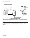
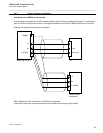
• Use the VHF adapter cable (P/N 3508 102 70850) together with the VHF plug and TNC plug to connect the
VHF and GPS antenna cables as well as the antennas.
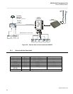
• The sensors, ECDIS, PC, pilot case, long range devices and auxiliary displays can be connected to the
MX535 transponder cabinet by the AIS cable or JB-50 Junction Box (optional). The device is driven by a
24V DC 7A supply, which is connected to the power terminal at the JB-50 Junction Box (optional). The AIS
should be connected to an emergency power source. A battery capacity calculation together with GMDSS-
equipment is needed! After performing these steps, the MX535 transponder automatically starts operation.
• The MX535 transponder has a ground terminal, which has to be connected to ship ground.