


MX535 UAIS Transponder Unit
Technical & Installation Manual
___________________________________________________________________________________________________________________
www.mx-marine.com
21
3.5 Installation of VHF / GPS Antennas
Interference to the Ship’s VHF Radiotelephone
The AIS ship borne equipment, like any other ship borne transceiver operating in the VHF maritime band, may
cause interference to a ship’s VHF radiotelephone. Because AIS is a digital system, this interference may occur as
a periodic (e.g. every 20 seconds) soft clicking sound on the ship’s radiotelephone. This may become more
noticeable if the VHF radiotelephone antenna is located close to the AIS VHF antenna, and when the
radiotelephone is operating on channels near the AIS operating channels (e.g. channels 27, 28 and 86).
Attention should be paid to the location and installation of the various antennas, in order to support the antenna
characteristics in the best possible way.
3.5.1 VHF Antenna Installation
Antenna Location
Location of the mandatory AIS VHF-antenna should be carefully considered. Digital communication is more
sensitive than analogue/voice communication to interference created by reflections caused by obstructions
such as masts and booms. It may be necessary to relocate the VHF radiotelephone antenna to minimize
interference effects.
To minimise interference effects, the following guidelines apply:
The AIS VHF antenna should have omni directional vertical polarisation providing 3 to 5 dB gain.
The AIS VHF antenna should be placed in an elevated position, as free standing as possible, with a minimum
of 2 metres in horizontal direction from constructions made of conductive materials. The antenna should not
be installed close to any large vertical obstruction. The AIS VHF antenna should have a visible sky of 360°.
The AIS VHF antenna should be installed at least 3 meters away from interfering high-power energy sources
such as radar and other transmitting radio antennas, and out of the way of the transmitting beam.
There should not be more than one antenna on each level. The AIS VHF antenna should be mounted directly
above or below the ship’s primary VHF radiotelephone antenna, with no horizontal separation and a minimum
of 2 metres vertical separation. If it is located on the same level as other antennas, the distance apart should
measure at least 10 metres.
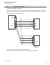
Cabling
The cable should be kept as short as possible to minimise attenuation of the signal. Double shielded coaxial
cables equal to or better than RG214 are recommended.
RG214 at VHF attenuation per meter of app. 0.07 dB/m (45m = 3.15db)
VHF AIS frequency app. 162MHz
All outdoor connectors on the coaxial cables should be fitted with preventive isolation, such as shrink-stocking
with silicone to protect the antenna cable against water penetration. Coaxial cables should be installed in
separate signal cable channels/tubes, and at least 10 cm away from any power supply cables. Crossing of
cables should take place at right angles (90°). Coaxial cables should not be exposed to sharp bends, which
may lead to changes to the characteristic impedance of the cable. The minimum bend radius should be 5
times the cables outside diameter.
Grounding
Coaxial down-leads must be used for all receiving antennas, and the coaxial screen should be connected to
the ground at one end.