


MX535 UAIS Transponder Unit
Technical & Installation Manual
____________________________________________________________________________________________
www.mx-marine.com
28
5.4 Testing
The Transponder Unit has neither traffic light indicators nor a display. Correct functioning cannot be made visible
directly.
To test the interfaces of the ship’s sensor inputs and the interface to the display unit, set the system in operation
and view the own ship’s (AIS1 Screen) data in the MKD. If the own ship AIS data are displayed, the interfaces are
working properly.
The VHF Transceiver can only be tested if a second AIS system is within the range of the Transceiver. The signals
of this AIS must be received and this second AIS must receive the signals of your own AIS.
6 Repair/Maintenance
GENERAL:
The jumper settings and switch settings on a replacement PCB must be the
same as on the defective PCB. The wire connections must be made in
exactly the same way. Exceptions are explained in this manual.
6.1 Trouble Shooting
6.1.1 Hints
In the case of problems during setting-to-work, the cabling should be checked again. All components must be
supplied with 24 VDC power.
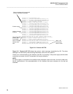
To get more information about the problem, read the system fault messages on the screen (MX420/MKD).
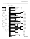
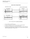
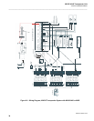
Test of the MX535 UAIS Transponder Output
1) Power down the system
2) Verify the connection of the MX420/MKD NMEA5 port to MX535 Channel 4 as shown in the picture
below.