MX535 UAIS Transponder Unit
Technical & Installation Manual
___________________________________________________________________________________________________________________
www.mx-marine.com
8
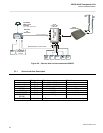
GYRO
ROT
LONG
RANGE
RTCM
SC 104
unit
Non-MX535
ECDIS/ARPA
Listener
CH 8
Ch2 (GLL,DTM,VTG)
CH 5
GPS
ANT.
VHF
ANT.
MX420/AIS
OR
MX420/MKD
MX-MARINE
SMART DGPS
ANTENNA
(NOT USED FOR MKD).
EXT.
GPS
CH 9
CH 4
MX420/MX535 communication
CH 1
CH
3
MX535
TRANSPONDER
JB-50
Junction Box
(optional)
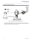
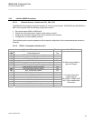
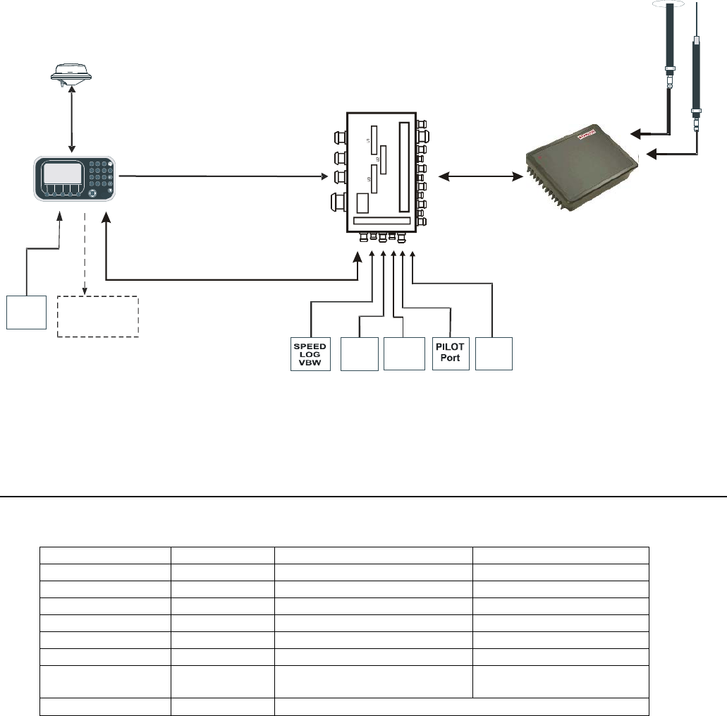
Figure 2.4 – Devices that can be connected to MX535
3.3.1 General Interface Description
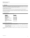
Interface Designation Speed Direction
Sensor 1 CH 1 4800 or 38400 bps Input
Sensor 2 CH 2 4800 or 38400 bps Input
Sensor 3 CH 3 4800 or 38400 bps Input
ECDIS CH 4 38400bps Input/Output
PILOT CH 5 38400bps Input/Output
LONG RANGE CH 8 38400bps Input/Output
DGPS (RTCM
SC104)
CH 9 9600bps Input
ALARM CIRCUIT CH 10 Dry relay contact (power off and alarm state closed)


