


mn100 Dual Digital Display
4
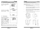
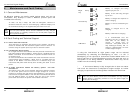
If there is no boat speed or change in heading registered on the
system for a period of 12 hours your Micronet instrument will switch
off to conserve power. A “POWER SAVE” alarm will sound before the
instrument system is switched off. Pressing any button within 10
seconds of the alarm sounding will allow the system to remain
switched on.
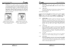
Backlighting will automatically shut down/off when operated in
daylight.
Artificial light WILL NOT recharge the battery. Placing
your Micronet instrument close to an artificial light will
seriously damage the instrument. Only recharge in natural
daylight.
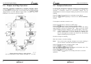
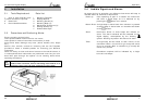
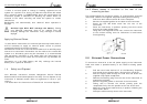
Applying External Power
In cases where instruments are mounted permanently below decks it
will be necessary to apply an external power source to prevent
complete discharge of the built in battery.
Connections on the rear of the instrument allow a 9V to 24V DC power
source to be connected. Connections can be made to the vessels DC
system or a 9V battery pack may be connected. It is recommended
that permanent connection is only made when the instruments are
permanently fixed to the vessel and not when the clip brackets are
used.
Connection to a 9V (PP3) battery will fully recharge the internal
battery over a period of 24 hours.
1.4 Safety and Disposal
Your Micronet instrument contains Manganese Lithium Dioxide
batteries which should be disposed of correctly. Do not dispose of any
instrument in domestic waste. Refer to regulations in force in your
country.
If in doubt return the instrument to Tacktick Ltd. for correct disposal.
Installation
33
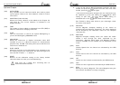
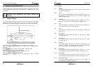
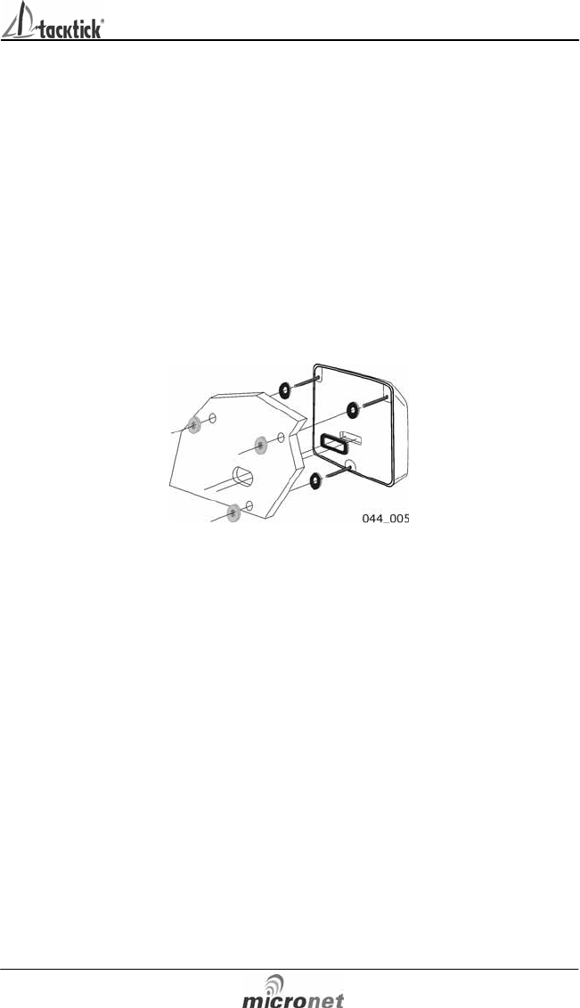
5.4.3 Where access is available to the rear of the
mounting surface
This method allows for maximum security of a permanently mounted
instrument. Position the supplied Template carefully before starting.
1. Drill three 5mm holes marked “B” on the Template.
2 Stick the 3 supplied gaskets on the back of the instrument.
3. Screw the four M4 brass studs into the rear of the
instrument.
4. Place the instrument in position pushing the three studs
through the newly drilled holes.
5. Using the three supplied thumb nuts, secure the instrument
to the surface making sure the instrument is level before
final tightening.
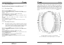
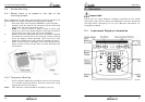
5.5 External Power Connections
To connect an external 9 to 24 volt power supply to the instrument
head from either a portable battery or the vessel’s existing power
system.
1. Drill two 7mm holes marked “P” on the Mounting Template
and smooth them together with a sharp knife or small file.
2. Pass the supply cable through the new hole and attach the
supplied crimp spade receptacles.
3. Remove the blanking plug from the rear of the instrument to
expose the terminals.
4 Stick the supplied gasket on the back of the instrument.
5. Taking care to connect the correct polarity push the
receptacles firmly onto the spades on the rear of the case.
6. Mount the instrument head securely in position following the
steps shown above.
7. Clamp the cable securely close to the instrument.