


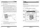
mn100 Dual Digital Display
32
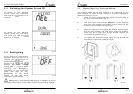
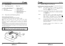
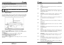
5.4 Surface Mounting
5.4.1 Where there is no access to the rear of the
mounting surface
Easy installation but will allow removal without gaining access to the
boat. Position the supplied Template carefully before starting.
1. Drill three 2mm holes marked “SURFACE” on the Template
2. Carefully snap the facia of the instrument off the main body
taking care not to drop the button pads. .
HINT – It may be useful to place a piece of sticky tape
across the front of the buttons before removing the facia to
prevent them from falling out during the installation.
3. Remove the three captive M4 nuts from the plastic moulding
and attach the instrument to the mounting surface using the
three self tapping screws provided. Take care not to over
tighten the screws as this may cause the moulding to crack.
4. Check the instrument is perfectly level, carefully position the
button inserts into the correct slots and snap the facia back
into position.
5.4.2 Temporary Mounting
1. Use the double sided tape provided to secure the instrument
to a suitable mounting surface. Press the instrument firmly
against the surface until secure.
Note: This method is recommended for temporary use only.
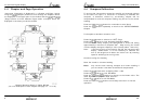
Operation
5
2 – Operation
Important:
Ensure that the “Auto Network” procedure described on the yellow
instruction sheet and full Setup and Calibration has been performed
correctly before attempting to use your Micronet instruments for
navigation purposes.
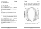
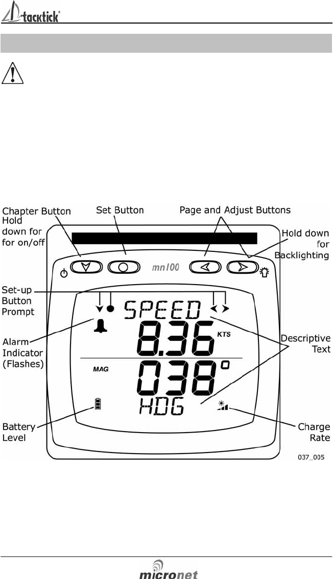
2.1 Instrument Display Information