


GB4000 BALLOON LIGHT• OPERATION AND PARTS MANUAL — REV. #1 (02/25/14) — PAGE 19
PREPARATION
1. Place the light tower in an area free of dirt and debris
with enough clearance as not to interfere with any
overhead obstructions. Make sure it is on secure level
ground with chock blocks underneath each wheel to
prevent the light tower from rolling.
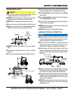
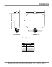
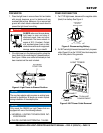
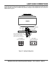
2. If the light tower is in the deployed position, place the
tower mast into the cradle support (stowed position).
See Figure 4. Make sure cradle lock/release pin has
been inserted and the mast is locked.
Figure 4. Light Tower in Stowed Position
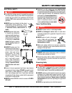
DANGER
ALWAYS make sure the area above
light tower is open and clear of
overhead power lines and other
obstructions. The tower extends in
excess of 30 ft. (9 meters). Contact
with overhead power lines or other
obstructions could result in equipment
damage, serious injury or death!
STOWED
POSITION
MAST
LOCK
NOTICE
The new lamp adapter plate requires no existing lamp
removal for installation. All lamps can remain in place
during installation of the adapter plate.
NOTICE
Only mount the GB4000 on Light Towers that are
equipped with one of the following ballasts:
• UNIVERSAL LIGHTING TECHNOLOGIES INC:
M1000120AC5M
• PHILIPS LIGHTING ELECTRONICNA : 71A-6592.
SETUP
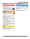
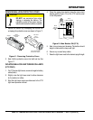
POWER DISCONNECTION
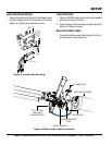
1. For LT12D light towers, disconnect the negative cable
(black) from battery. See Figure 5.
Figure 5. Disconnecting Battery
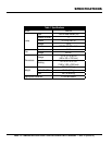
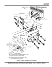
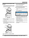
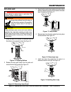
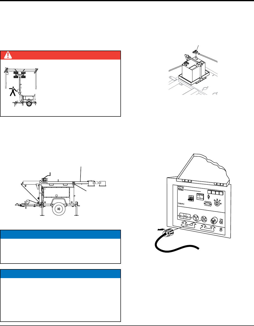
2. For MLT series light towers disconnect the 4-pin power
cable (Figure 6) from the 120 VAC twist-lock receptacle
on the front panel of the generator.
Figure 6. MLT Power Cable Removal
DISCONNECT
NEGATIVE
BATTERY CABLE
IDLE CONTROL
0 0
0
0
0
HOURS
ON
OFF
WHISPERWATT
7KW AC
Model DA-7000SS
7000 WATT
DIESEL POWERED AC GENERA
TOR
STARTER SWITCH
RUN
HEA
T
START
STOP
HOUR METER
AC VOL
TMETER
AC CIRCUIT
BREAKER
120/240V
25A
25A
120V
20A
25A
MLT
LIGHT TOWER
TO BALLAST
COMPAR
TMENT
4-PIN POWER
CABLE
DISCONNECT