


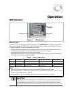

Operation
14 900-0112-01-00 Rev B
Search
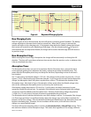
An automated search circuit is available to minimize the power draw when no loads are present.
When enabled, the inverter does not always deliver full output. The output is reduced to brief pulses
with a delay between them. These pulses are sent down the output lines to see if a resistance is
present. In effect, the pulses “search” for a load. If one is detected, the inverter’s output increases to
full voltage so that it can power the load. When the load is turned off, the inverter “goes to sleep” and
begins searching again.
The sensitivity of Search mode is in increments of approximately 0.1 Aac. The default is 6 increments,
or 0.6 Aac. A load which draws this amount or greater will “wake up” the inverter.
NOTE:
Due to changing load characteristics, these increments are only approximate and may not
function exactly as listed.
The pulse duration and the delay both have a time period that is measured in AC cycles. These two
items and the load detection threshold are adjustable.
¾
Search mode can save a considerable amount of power, particularly in smaller systems with intermittent use.
¾
Search mode may not be useful in larger systems with loads that require continuous power (e.g., clocks,
answering machines, fax machines). Search mode may cause nuisance shutdowns, or it may sleep so rarely
that there is no benefit.
¾
Some devices may not be easily detectable by Search mode.
Input
When the GFX inverter input terminals are connected to a stable AC source, the inverter will
synchronize itself with that source and use it as the primary source of AC power. (See “AC Source
Acceptance” on page 15.) In this situation, the transfer relay will engage, linking the AC source directly
with the inverter’s output. It can also use the source to charge batteries. (See “Transfer” on page 16
and “Battery Charging” on page 18.)
¾
Two sets of input criteria are available, one for the utility grid and one for a generator. Only one source can
be selected at a time. In the MATE system display, the source is selected using the
ac transfer control
menu.
In the MATE3 system display, it is selected using either the
Inverter Input Select
or the
AC Input and Current
Limit
menus. See the system display manual for more information. (For other aspects of input selection, see
the items below. Also see AC Current Settings on page 15.) Both grid and generator criteria are adjustable.
¾
The grid-interactive function can sell power using the input connection. (See the section entitled “Selling” on
page 24.) In the MATE, this function only operates if
grid
is selected in the
ac transfer control
menu. It does
not function if
gen
is selected.
¾
The Input Support feature can use battery power to assist a smaller AC source. (See the section entitled
“Input Support” on page 17.)
¾
There are a number of considerations when selecting the type and size of an AC generator. (See the section
entitled “Generators” on page 16.)
¾
The AC input current is used to power both loads and battery charging. The total should not exceed the size
of the AC overcurrent device or AC source. These devices should be sized appropriately during planning.
¾
The loads powered by the inverter
must not
exceed the size of the inverter’s transfer relay. (See the section
entitled “Transfer” on page 16.)
CAUTION: Equipment Damage
Current draw in excess of the inverter’s transfer relay rating can damage the transfer
relay. This damage is not covered by warranty.