


Table of Contents
900-0112-01-00 Rev B 5
List of Tables
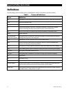
Table 1 Terms and Definitions..................................................................................................................... 2
Table 2 Battery LED Values..........................................................................................................................11
Table 3 Status LED Quick Reference ........................................................................................................12
Table 4 Basic Troubleshooting Steps ......................................................................................................31
Table 5 Error Troubleshooting...................................................................................................................37
Table 6 Warning Troubleshooting............................................................................................................38
Table 7 Disconnect Troubleshooting......................................................................................................39
Table 8 Stop Sell (and Charge) Reasons .................................................................................................40
Table 9 Electrical Specifications (GFX1312E)........................................................................................43
Table 10 Mechanical Specifications (GFX1312E)...................................................................................43
Table 11 Electrical Specifications (GFX1424E)........................................................................................44
Table 12 Mechanical Specifications (GFX1424E)...................................................................................44
Table 13 Electrical Specifications (GFX1448E)........................................................................................45
Table 14 Mechanical Specifications (GFX1448E)...................................................................................45
Table 15 Environmental Specifications for All Models........................................................................46
Table 16 Interconnection Response to Voltage and Frequency .....................................................46
Table 17 12-Volt Inverter Settings (MATE) ...............................................................................................47
Table 18 24-Volt Inverter Settings (MATE) ...............................................................................................48
Table 19 48-Volt Inverter Settings (MATE) ...............................................................................................49
Table 20 12-Volt Inverter Settings (MATE3).............................................................................................50
Table 21 24-Volt Inverter Settings (MATE3).............................................................................................51
Table 22 48-Volt Inverter Settings (MATE3).............................................................................................52
List of Figures
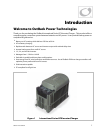
Figure 1 International Series GFX Inverter/Charger .............................................................................. 7
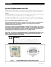
Figure 2 MATE3 and MATE System Display and Controller................................................................ 8
Figure 3 AC Wiring Compartment................................................................................................................ 9
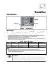
Figure 4 LED Indicators...................................................................................................................................11
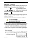
Figure 5 Charging Stages Over Time.........................................................................................................18
Figure 6 Repeated Charging Cycles...........................................................................................................21
Figure 7 OutBack HUB4 and MATE.............................................................................................................25
Figure 8 Example of Parallel Stacking Arrangement (Three Inverters) ........................................26
Figure 9 Example of Three-Phase Stacking Arrangement (Three Inverters) ..............................26