


Operation
900-0112-01-00 Rev B 23
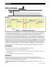
The inverter, when equipped with the Remote Temperature Sensor (RTS), will compensate for changes
in temperature. The RTS is attached to a single battery near the center of the bank, to achieve a
representative temperature. If installed in a multiple-inverter system, only a single RTS is necessary. It
must plug into the master inverter and will control the charging of all slaves and all charge controllers.
(See the International Series GFX Installation Manual to locate the RTS port.) This process is automatic.
When charging, an inverter system with an RTS will increase or decrease the charge voltage by 5 mV
per degree Celsius per battery cell. This setting affects the Absorption, Float, and Equalization set
points. The Sell RE and Refloat set points are not temperature compensated. The Equalization set
points are not compensated in OutBack charge controllers.
¾
In a 12 Vdc system (6 cells, 2 volts each), this means 0.03 volts per degree Celsius above or below 25°C.
Maximum compensation is ± 0.6 Vdc.
¾
In a 24 Vdc system (12 cells, 2 volts each), this means 0.06 volts per degree Celsius above or below 25°C.
Maximum compensation is ± 1.2 Vdc.
¾
In a 48 Vdc system (24 cells, 2 volts each), this means 0.12 volts per degree Celsius above or below 25°C.
Maximum compensation is ± 2.4 Vdc.
Examples:
¾
A 12 Vdc system with batteries at 10°C will compensate its charging to 0.45 Vdc
higher
than the set points.
¾
A 24 Vdc system with batteries at 35°C will compensate its charging to 0.6 Vdc
lower
than the set points.
¾
A 48 Vdc system with batteries at 15°C will compensate its charging to 1.2 Vdc
higher
than the set points.