Operation
26 900-0112-01-00 Rev B
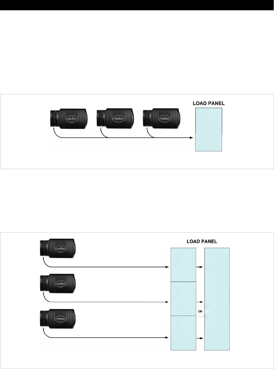
Parallel Stacking (Dual-Stack and Larger)
In parallel stacking, two or more inverters are stacked to create a single, common 230 Vac output.
¾
The master provides the primary output. The slaves are connected to the same output and assist the master.
¾
The slave inverters can be programmed to activate on demand, reducing idle-power consumption. They will
remain off until the loads exceed a certain threshold.
¾
A two-inverter system can continuously power 2.6 to 2.8 kVA of loads, depending on the inverter model.
¾
Up to ten inverters may be installed in a parallel arrangement. The example on this page shows
three inverters.
Figure 8 Example of Parallel Stacking Arrangement (Three Inverters)
Three-Phase Stacking
In three-phase stacking, three inverters are stacked to create three separate 230 Vac output legs.
These outputs are 120° out of phase. Any two outputs produce 400 Vac between them. The three
outputs can be used to power three-phase loads when all inverters work together.
¾
A three-phase system can continuously power 3.9 kVA to 4.2 kVA of loads, depending on the inverter model.
¾
Only three inverters, one per phase, may be installed in a three-phase arrangement.
Figure 9 Example of Three-Phase Stacking Arrangement (Three Inverters)
1.3 kVA 230 Vac
1.3 kVA 230 Vac
1.3 kVA 230 Vac
1.3 kVA
230 Vac
3.9 kVA
400 Vac
1.3 kVA
230 Vac
1.3 kVA
230 Vac
3.9 kVA
230 Vac
1.3 kVA 230 Vac
1.3 kVA 230 Vac
1.3 kVA 230 Vac


