


16 C1570M-C (5/06)
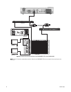
BASIC HARDWARE CONNECTIONS
CM9700-CC1 CONNECTION
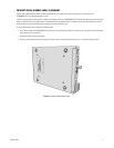
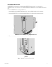
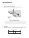
Use the 16-pin terminal block for the RS-422 serial connection (Pelco P protocol) between the CM9700MDD-EVS and the CM9700-CC1.
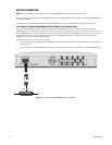
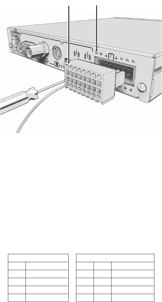
The terminal block has tension clamps instead of screw terminals. Use a small screwdriver to open the clamp for a particular lead. Figure 11 shows
how to wire the terminal block and connect it to the CM9700MDD-EVS.
NOTE: The terminal block can be attached to the CM9700MDD-EVS only in the proper position, as shown in Figure 11.
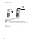
Figure 11. Wiring the CM9700MDD-EVS Terminal Block
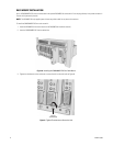
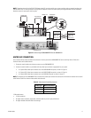
1. Use a Cat5e (or better) cable (user-supplied) with an RJ-45 connector at one end and with the individual wires exposed at the other end to
connect the CM9700MDD-EVS to the CM9700-CC1.
2. Connect the cable’s individual wires to the terminal block on the rear panel of the CM9700MDD-EVS. An arrow on the rear panel identifies
pin 1; on the terminal block, pin 1 is the leftmost lead on the top row and pin 9 is the leftmost lead on the bottom row (refer to Figure 11).
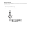
Figure 12 illustrates the cable connections on each end.
3. Insert the cable’s RJ-45 connector into any available RS-422 COM port on the CM9700-CC1.
NOTE: When connecting peripheral equipment to the CM9700-CC1 serial communication ports, shielded cabling is required to comply with CE
emissions guidelines.
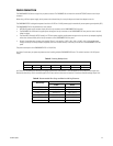
Table A identifies the RS-422 pin assignments on the CM9700MDD-EVS and the CM9700-CC1. Note that the alarm and relay inputs on the
CM9700MDD-EVS are reserved for future use, and are not included in this table.
Table A. RS-422 Pin Assignments
CM9700-CC1 CM9700MDD-EVS
Pin Lead Pin Label Lead
1 RS-422 Data TX+ 1 TX
-
RS-422 Data TX
-
2 RS-422 Data TX
-
2RX
-
RS-422 Data RX
-
7 RS-422 Data RX
-
9 TX+ RS-422 Data TX+
8 RS-422 Data RX+ 10 RX+ RS-422 Data RX+
PIN 1 PIN 1