


C1570M-C (5/06) 17
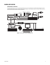
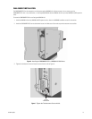
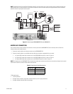
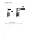
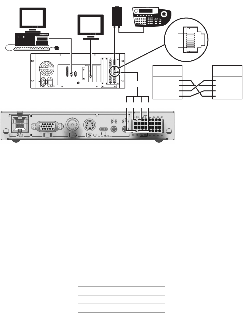
NOTE: Remember that the first few RS-422 COM ports on the CC1 must be used for one or more matrix bays and any network interface units
and hot switch units. For more information on using RS-422 COM ports, refer to the matrix system port assignment table and the Installation/
Operation manual for your specific matrix system.
Figure 12. Connecting the CM9700MDD-EVS to the CM9700-CC1
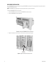
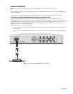
MATRIX BAY CONNECTION
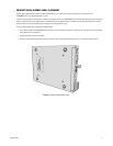
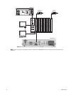
Use a coaxial cable to connect the Video Out connector on the rear panel of the CM9700MDD-EVS to the matrix bay. Refer to Table A for
maximum video coaxial cable distances.
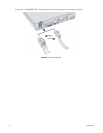
1. Connect the coaxial cable to the video out connector on the CM9700MDD-EVS.
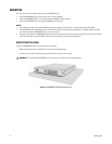
2. Connect the coaxial cable to any available matrix bay video input connector as appropriate for your system:
• In a System 9760, video input connectors are on the CM9760-MXB rear panel, as shown in Figure 13
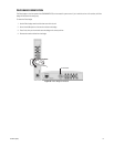
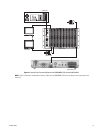
• In a System 9770, video input connectors are on the CM9770-MXB rear panel, as shown in Figure 14.
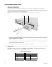
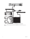
• In a System 9780, video input connectors are on the CM9700-VPP panel, as shown in Figure 15.
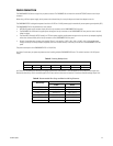
NOTE: The distance from the CM9700MDD-EVS to the matrix bay video input connector must be less than the maximum distance for the coaxial
cable. Refer to Table B for maximum video coaxial cable distances.
Table B. Video Coaxial Cable Requirements
*Cable requirements:
• 75-ohm impedance.
• All-copper center conductor; steel-center conductor cable may result in poor performance.
• All-copper braided shield with 95% braid coverage.
Cable Type* Maximum Distance
RG59/U 750 ft (229 m)
RG6/U 1,000 ft (305 m)
RG11/U 1,500 ft (457 m)
CM9700-CC1
PRINTER COM1 COM2
CM9700-MGR
VGA MONITOR
RX-TX+ TX- RX+
CM9700-CC1
RJ45 PIN ASSIGNMENTS
CM9700MDD-EVS
PIN 1 = TX+
PIN 2 = TX-
PIN 7 = RX-
PIN 8 = RX+
PIN 1 = TX-
PIN 2 = RX-
PIN 9 = TX+
PIN 10 = RX+
RS-422
CM9505-UPS
CM9760-KBD
PIN ASSIGNMENTS
PIN 1
PIN 8
CM9700MDD-EVS